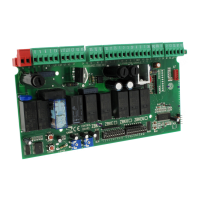
Do you have a question about the CAME ZBKE and is the answer not in the manual?
| Brand | CAME |
|---|---|
| Model | ZBKE |
| Category | Motherboard |
| Language | English |
Input for 230V AC power supply to the control unit.
Connection for a 230V AC single-phase motor.
230V AC output for signaling devices like flashing lights.
Power supply for accessories, max 20W, 24V AC.
Connection for a 230V cycle lamp or courtesy light.
Normally Open (N.O.) contact for radio or button control.
Normally Closed (N.C.) contact for a stop pushbutton.
Normally Open (N.O.) contact for partial opening control.
Normally Open (N.O.) contact for opening control.
Normally Open (N.O.) contact for closing control.
Output for simultaneous control of two combined motors.
Connection terminal for the radio control antenna.
Normally Closed (N.C.) contact for re-opening during closure.
Normally Closed (N.C.) contact for re-closing during opening.
Normally Closed (N.C.) contact for partial stop function.
Normally Open (N.O.) contact output with 5A rating.
Activates automatic gate closure after opening.
Enables open-stop-close-stop sequence via button/remote.
Enables open-close sequence via button/remote.
Enables opening-only operation via radio control.
Requires constant button press for operation, deactivates remote.
Activates pre-flashing signal during opening and closing.
Enables obstacle detection safety feature.
Enables re-opening during closing phase with safety device.
Enables partial stop function with safety device.
Enables total stop function via button on terminals 1-2.
Sets the unit to operate as a slave in a paired connection.
Partial opening with fixed 8-second automatic closing.
Partial opening with adjustable automatic closing via trimmer.
Activates safety test for photocell efficiency check.
Sets the unit to operate as a master in a paired connection.
Function for spare limit switch programming (for ZBKE only).
Enables courtesy light function.
Enables cycle lamp function.
Procedure for inserting the AF radiofrequency board.
Instructions for coding the radio transmitter.
Steps to memorize the transmitter code on the control board.
Function of CH1 for direct control of motor unit functions.
Function of CH2 for direct control of accessory devices.
Procedure to set the close limit switch.
Procedure to set the open limit switch.
Reversing motor and encoder connections if LED is off.
Electrical connections for photocell safety test setup.
Enables the safety test function via dip switch 13.
How the control unit checks photocell efficiency after each command.
Important checks for safety test, avoiding bridges on specific contacts.
Matching motor rotation directions for combined operation.
Designating master and slave motors in a paired system.
Ensuring the radio receiver is connected only to the MASTER board.
Using dip-switches to select desired functions for paired motors.
Electrical connections and selections for the master control board.
Configuration of the slave control board, disabling unused dip switches.
 Loading...