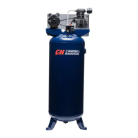
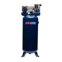
Modelos Verticales
23 Sp
Manual de Instrucciones
Problema Posible(s) Causa(s) Acción a Tomar
Aceite excesivo en el aire
de descarga. NOTA: En un
compresor lubricado con
aceite siempre hay una
pequeña cantidad de aceite
en el flujo de aire.
Agua en el aire de salida o
en el tanque
El motor zumba y funciona
lentamente o no funciona
en lo absoluto
El mecanismo de reajuste
interrumpe el
funcionamiento
constantemente o los
fusibles se funden con
frecuencia
El tanque no mantiene la
presión cuando el
compresor está apagado y
la válvula de cierre está
cerrada
El interruptor de presión
tira continuamente aire por
la válvula de descarga
El interruptor de presión no
libera el aire cuando la
unidad de apaga
Vibración excesiva
1. Aros del émbolo desgastados
2. La entrada de aire del compresor
está restringida
3. Demasiado aceite en el compresor
4. Viscosidad del aceite equivocada
1. Operación normal. La cantidad
de agua aumenta con el clima
húmedo
1. Utiliza un cordón de extensión
2. Malfuncionamiento de la válvula
de verificación o de la válvula de
descarga
3. Voltaje bajo
4. Malfuncionamiento del
interruptor presión, los contactos
no se cierran
1. Demasiados aparatos en el mismo
circuito
2. Tamaño incorrecto del fusible o
del disyuntor
3. Malfuncionamiento de la válvula
de verificación
4. Interruptor de presión fijado
demasiado alto
5. Cableado flojo
6. Malfuncionamiento del motor
1. Válvula desgastada
2. Verifique todas las conexiones y
los accesorios para detectar fugas
3. Revise el tanque para detectar
fisuras o perforaciones
1. Malfuncionamiento de la
válvula
1. Malfuncionamiento de la válvula
de descarga en el interruptor de
presión
1. Ajustadores flojos
2. La correa necesita ser reempla-
zada
3. Alineación de la correa
1. Reemplácelos con aros nuevos. Mantenga el nivel de aceite y
cambie el aceite con más frecuencia.
2. Limpie el filtro. Verifique otras restricciones en el sistema de entrada.
3. Escúrralo hasta que alcance el nivel de lleno.
4. Use Mobil 1® 10W-30.
1. Drene el tanque con más frecuencia. Al menos diariamente.
2. Agregue un filtro
1. No utilice un cordón de extensión. Utilice una manguera de aire
más larga con un diámetro mayor.
2. Reemplace la válvula de verificación, la válvula de descarga o el
interruptor de presión.
No desarme la válvula con
presión de aire en el tanque.
3. Verifique con un voltímetro, revise el interruptor de reajuste del
motor. Si este se dispara varias veces, busque la causa y corríjala.
Consulte el siguiente punto.
4. Repare o reemplace el interruptor de presión.
1. Use sólo el compresor de aire en el circuito.
2. Asegúrese de que los fusibles o los disyuntores sean del tamaño
adecuado.
3. Reemplace la válvula de verificación
No desarme la válvula con
presión de aire en el tanque.
4. Ajuste o reemplace el interruptor.
5. Verifique todas las conexiones eléctricas
6. Reemplace el motor.
1. Reemplace la válvula.
No desarme la válvula con
presión de aire en el tanque
.
2. Apriete.
3. Reemplace el tanque. Nunca repare un tanque dañado
1. Reemplace la válvula de verificación si la válvula de descarga tiene
perdidas constantemente.
No desarme la válvula con
presión de aire en el tanque.
1. Reemplace el interruptor de presión si éste no libera la presión por
un breve período de tiempo cuando se apaga la unidad.
No desarme el interruptor de
presión si hay presión en el
tanque.
1. Ajústelos.
2. Reemplace la correa con otra del tamaño adecuado.
3. Alinee el volante y la polea.
!
PELIGRO
!
PELIGRO
!
PELIGRO
!
PELIGRO
!
PELIGRO
Guía de Diagnóstico de Averías (Continuación)
pressure reaches the maximum preset
pressure. After air is used from the
tank and drops to a preset low level,
the pressure switch automatically turns
the motor back on. In the "off"
position, the compressor will not
operate. This switch should be in the
"off" position when connecting or
disconnecting the power cord from the
electrical outlet.
When the pressure switch turns the
motor off you will hear air leaking out
of the pressure switch unloader valve
for a short time. This releases the air
pressure from the discharge tube and
allows the compressor to restart easier.
For units without a manual switch,
whenever the procedures call for
turning the switch to the OFF position,
use the switch at the disconnect
instead.
Unloader - Device on pressure switch
which allows pressurized air to vent
alleviating motor restarts under load.
Regulator - The regulator controls the
amount of air pressure released at the
hose outlet (Sold separately).
ASME Safety Valve - This valve
automatically releases air if the tank
pressure exceeds the preset maximum.
Discharge tube - This tube carries
compressed air from the pump to the
check valve. This tube becomes very
deterioration, weakness or leakage.
Repair or replace defective items
before using.
8. Check all fasteners at frequent
intervals for proper tightness.
Motors, electrical
equipment and controls
can cause electrical arcs
that will ignite a
flammable gas or vapor. Never operate
or repair in or near a flammable gas or
vapor. Never store flammable liquids
or gases in the vicinity of the
compressor.
Never operate compressor
without a beltguard. This
unit can start automatically
without warning. Personal
injury or property damage could occur
from contact with moving parts.
9. Do not wear loose clothing or
jewelry that will get caught in the
moving parts of the unit.
Compressor parts may be
hot even if the unit is
stopped.
10. Keep fingers away from a running
compressor; fast moving and hot
parts will cause injury and/or burns.
11. If the equipment should start to
vibrate abnormally, STOP the
engine/motor and check
immediately for the cause. Vibration
is generally a warning of trouble.
12. To reduce fire hazard, keep
engine/motor exterior free of oil,
solvent, or excessive grease.
An ASME code
safety relief valve
with a setting no higher than 150 psi
MUST be installed in the tank for this
compressor. The ASME safety valve
must have sufficient flow and pressure
ratings to protect the pressurized
components from bursting.
See compressor
specification decal
for maximum operating pressure. Do
not operate with pressure switch or
pilot valves set higher than the
maximum operating pressure.
13. Never attempt to adjust ASME
safety valve. Keep safety valve free
from paint and other accumulations.
Never use plastic
(PVC) pipe for
compressed air. Serious injury or death
could result.
!
WARNING
!
CAUTION
!
WARNING
!
CAUTION
!
WARNING
!
WARNING
2
Operating Instructions
Stationary Air Compressor
Never attempt to repair or
modify a tank! Welding,
drilling or any other
modification will weaken the tank
resulting in damage from rupture or
explosion. Always replace worn,
cracked or damaged tanks.
Drain liquid from
tank daily.
14.
Tanks rust from moisture build-up,
which weakens the tank. Make sure
to drain tank regularly and inspect
periodically for unsafe conditions
such as rust formation and corrosion
.
15. Fast moving air will stir up dust and
debris which may be harmful. Release
air slowly when draining moisture or
depressurizing the compressor system.
SPRAYING PRECAUTIONS
Do not spray flammable
materials in vicinity of
open flame or near
ignition sources including
the compressor unit.
16. Do not smoke when spraying paint,
insecticides, or other flammable
substances.
17. Use a face mask/
respirator when
spraying and spray in a
well ventilated area to
prevent health and fire
hazards.
18. Do not direct paint or other
sprayed material at the compressor.
Locate compressor as far away from
the spraying area as possible to
minimize overspray accumulation
on the compressor.
19. When spraying or cleaning with
solvents or toxic chemicals, follow
the instructions provided by the
chemical manufacturer.
Refer to Figure 2.
INSTALLING A SHUT-OFF VALVE
A shut-off valve should be installed on
the discharge port of the tank to
control the air flow out of the tank.
The valve should be located between
the tank and the piping system.
Pressure switch - Auto/Off Switch - In
the "auto" position, the compressor
shuts off automatically when tank
General Safety (Con’t)
Introduction
Drain Petcock
Discharge Tube
Belt Guard
Check
Valve
Safety
Valve
Pressure
Switch
Tank
Outlet
Figure 2
Tank Drain Valve
Tank
Pressure
Gauge
 Loading...