22 Sp
Manual de Instrucciones
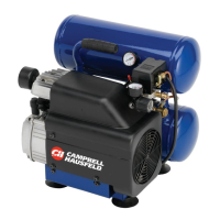
Compresores de Aire Estacionarios
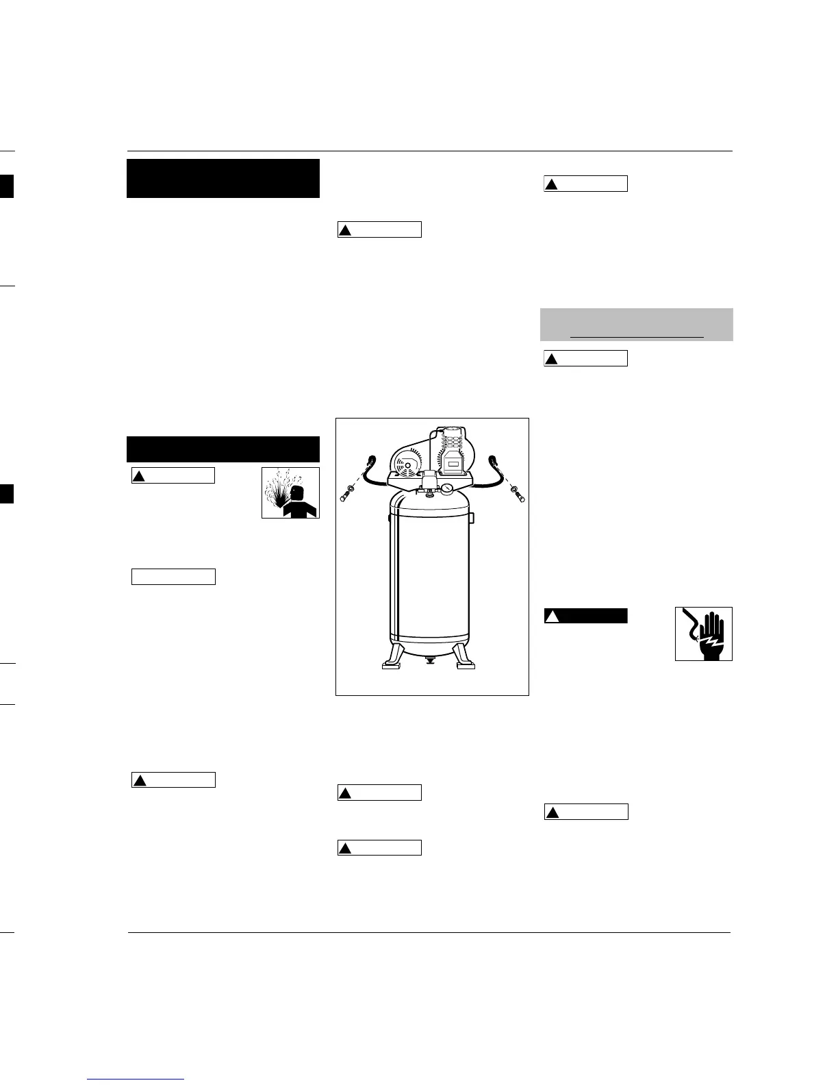
debe ser sólo una 12,7 mmm (1/2”) al
aplicarle una fuerza de 2,27 kg entre la
polea del motor y el cabezal (Vea la
Figura 9).
PARA AJUSTAR LA BANDA:
1. Quítele la tapa.
2. Aloje los cuatro tornillos que
sostienen el motor a la base.
3. Mueva el motor en la dirección
adecuada. La banda debe estar bien
alineada al hacer este ajuste.
4.
Ajuste el volante o la polea del motor
para que la banda corra derecha.
5. Si es necesario, use un sacaengranaje
para mover la polea en el eje del
motor. Apriete el tornillo después de
terminar de mover la polea.
6. Colóquele la tapa de la banda.
ALMACENAMIENTO
1. Cuendo no los esté usando,
almacene la manguera y el
compresor en un sitio frío y seco.
2. Debe drenar la humedad del
tanque y desconectar la manguera y
colgarla con los extremos hacia
abajo para drenarla.
3. Para proteger el cordón eléctrico,
enróllelo en el mango de la unidad
o enróllelo y amárrelo.
INFORMACION TECNICA
Para recibir información sobre el
funcionamiento o reparación de la
unidad, sírvase llamar al 1-800-543-
6400 (en EUA). En el exterior,
comuníquese con el distribuidor
autorizado más cercano a su domicilio.
Mida el Nivel de Aceite ●
Drene el Tanque ●
Chequée el Filtro de Aire ●
Chequée la Válvula de Seguridad ●
Limpie la unidad ●
Chequée la Tensión de las Bandas ●
Cámbiele el Aceite ●
MANTENIMIENTO
Servicio Necesario
Diaria- Semanal- Mensual- Trimestral-
mente mente mente mente
Deflexión de 1,27 cm (1/2”)
Figura 9
Mantenimiento
(Continuación)
Problema Posible(s) Causa(s) Acción a Tomar
Baja presión de descarga
El sobrecalentamiento de la
bomba derrite el filtro
Ruido excesivo (golpeteo)
1. La demanda de aire excede la
capacidad de la bomba
2. Pérdidas de aire
3. Entrada de aire restringida
4. Juntas defectuosas
5. Válvulas dañadas o con pérdidas.
1. No está la junta de aislamiento
entre el filtro y el cabezal
2. Válvulas rotas/juntas defectuosas
1. Motor o polea del compresor floja
2. Falta de aceite en el cárter
3. Biela gastada
4. Diámetros del eje del émbolo
desgastados
5. El émbolo pega contra la placa de
la válvula
6. Válvula de verificación ruidosa en el
sistema del compresor
1.
Reduzca la demanda de aire o utilice un compresor de mayor capacidad.
2. Escuche para detectar pérdidas de aire. Aplique una solución jabonosa a
todos los accesorios y conexiones. Aparecerán burbujas en los puntos
donde existan pérdidas. Ajuste o reemplace los accesorios o conexiones
con pérdidas.
3. Limpie el elemento del filtro de aire.
4.
Reemplace cualquier junta que pruebe estar defectuosa al inspeccionarla.
5. Quite el cabezal e inspecciónelo para detectar posibles roturas de la
válvula, válvulas desalineadas, asientos de válvulas dañados, etc.
Reemplace las piezas defectuosas y vuelva a armar.
Instale una nueva junta
para el cabezal cada vez que
éste sea quitado.
1. Instale la junta.
2. Reemplace las válvulas o instale una junta nueva.
1. Es común que el motor o las poleas del compresor flojas causen golpeteo
de los compresores. Ajuste los tornillos de los sujetadores de la polea y los
tornillos de montaje.
2. Controle si el nivel de aceite es el adecuado; si está bajo, verifique la
posibilidad de que los cojinetes estén dañados. El aceite sucio puede
causar un desgaste excesivo.
3. Reemplace la biela. Mantenga el nivel de aceite y cambie el aceite con
más frecuencia.
4. Quite los ensamblajes del émbolo del compresor e inspecciónelos para
detectar un desgaste excesivo. Reemplace el eje del émbolo(s) si está
excesivamente desgastado o según necesario.
Mantenga el nivel de aceite
y cambie el aceite con más frecuencia.
5. Quite el cabezal del compresor y la placa de la válvula e inspeccione para
detectar depósitos de carbón u otros elementos extraños en la cabeza del
émbolo. Vuelva a colocar el cabezal y la placa de la válvula utilizando una
junta nueva. Consulte la sección de lubricación para el aceite
recomendado.
6. Reemplácela.
No desarme la válvula
de verificación con presión de aire
en el tanque.
Guía de Diagnóstico de Averías
PIPING
Never use plastic
(PVC) pipe for
compressed air. Serious injury or death
could result.
Any tube, pipe, or hose used must have
a pressure rating higher then 150 psi.
Minimum recommended pipe size:
- up to 50 feet long use 1/2”
- greater than 50ft. long use 3/4”
Larger diameter pipe is always better.
All wiring and
electrical
connections must be performed by a
qualified electrician. Installations must
be in accordance with local and
national codes.
GROUNDING
This product must be grounded. If the
unit comes with a factory installed
cord, plug the cord into a properly
sized, grounded outlet. For units that
do not have a factory installed cord,
install permanent wiring from the
electrical source to the pressure switch
with a ground conductor connected to
the grounding screw on the pressure
switch. A properly sized cord with a
ground conductor and plug may also
be installed by the user.
Improperly grounded
motors are shock hazards.
Make sure all the
equipment is properly grounded.
WIRING
Local electrical wiring codes differ from
area to area. Source wiring, plug and
protector must be rated for at least the
amperage and voltage indicated on the
motor nameplate, and meet all electrical
codes for this minimum. Use a slow blow
fuse type T or a circuit breaker.
Overheating, short
circuiting and fire
damage will result from inadequate
wiring.
Motor protection should be used when
a motor built-in thermal overload
protection is not provided. Some 3
phase units require a magnetic starter
!
CAUTION
!
DANGER
!
WARNING
!
WARNING
(Part number MP3445 available
separately). Do not draw bolts tight.
Allow the pads to absorb vibrations. A
flexible coupling should be installed
between the tank and service piping.
This compressor is
extremely top
heavy. The unit must be bolted to the
floor with isolation pads or secured
with the wall cable (if provided)
before operating to prevent
equipment damage, injury or death.
WALL CABLE INSTALLATION
(Provided on some 30 gallon models)
Included with the safety cable are two
lag screws and washers.
1. Place an isolation pad beneath each
foot of the compressor to minimize
vibration.
2. Position the cable through the
baseplate as shown in Figure 3.
3. Place the screws through the
washers then through looped ends
of cable.
4. Secure the screws to a stud within a
framed wall. Use anchors if the wall
is concrete.
Do not secure the
compressor with
toggle bolts into drywall. Drywall
sheeting or plaster will not support
the weight of the compressor.
Never install a
shut-off valve
between the compressor pump and the
tank. Personal injury and/or equipment
damage may occur.
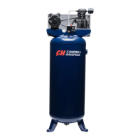
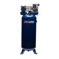
Vertical Models
3
Operating Instructions
hot during use. To avoid the risk of
severe burns, never touch the
discharge tube.
Check valve - One-way valve that
allows air to enter the tank, but
prevents air in the tank from flowing
back into the compressor pump.
Belt Guard - Covers the belt, motor
pulley and flywheel.
Tank Drain Valve - This valve is
located on the bottom of the tank. Use
this valve to drain moisture from the
tank daily to reduce the risk of
corrosion.
Reduce tank pressure below 10 psi,
then drain moisture from tank daily to
avoid tank corrosion. Drain moisture
from tank(s) by opening the drain
valve located underneath the tank.
Disconnect, tag and lock
out power source, then
release all pressure from
the system before
attempting to install, service, relocate
or perform any maintenance.
LOCATION
This compressor is
not intended for
outdoor installation.
It is extremely important to install the
compressor in a clean, well ventilated
area where the surrounding air
temperature will not be more than 100°F.
Provide a minimum clearance of 18
inches between the compressor
flywheel or fan to the wall and ensure
clear access to the drain cock to
facilitate condensate drainage.
Do not locate the compressor air inlet
near steam, paint spray, sandblast areas
or any other source of contamination.
MOUNTING
Never use the
wood shipping
skids for mounting the compressor.
FLOOR MOUNTING
(All Units)
On some 30 gallon models a wall cable
is provided and should be installed. If
the unit is not secured with the wall
cable, the compressor feet MUST be
bolted to a flat, even, concrete floor or
separate concrete foundation.
Vibration isolators must be used
between the tank leg and the floor
Figure 3 - Wall Cable Installation
Electrical Installation
HARD WIRED UNITS ONLY
Installation
Introduction
(Continued)
 Loading...