Do you have a question about the Canon DR-2580C and is the answer not in the manual?
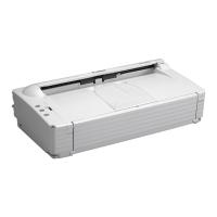
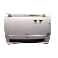
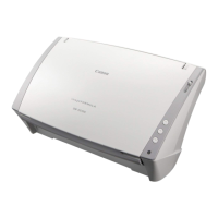
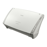
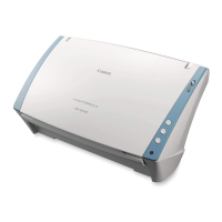
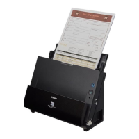
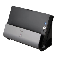
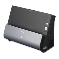
Highlights key product features like compact design, high-speed scanning, dual-path mechanism, and optional flatbed scanner.
Details technical specifications including dimensions, weight, power requirements, operating environment, and interface options.
Covers essential safety precautions regarding electrical hazards, modifications, and handling to prevent injury or damage.
Identifies major external components of the scanner, illustrating their locations on the front, rear, and side views.
Explains fundamental user operations such as initial installation, software interaction, and basic scanner functions like clearing jams.
Provides instructions for routine user maintenance, including cleaning procedures and roller replacement guidance.
Offers a high-level overview of the scanner's basic configuration, detailing its main systems and their interconnections.
Explains the scanner's reading system, including the CIS sensor, optical unit, and shading correction process for image capture.
Details the mechanics of document feeding, including pickup, separation by retard roller, and ejection paths (U-turn/Straight).
Describes the control PCB's role in managing scanner operations, illustrating its block diagram and key sections.
Explains the image processing techniques performed by the scanner and computer, covering adjustments, enhancements, and conversion methods.
Details the power supply system, including AC adapter specifications, voltage distribution, and power saving features.
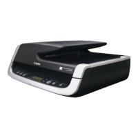
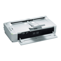
Covers the specifications and functionality of the optional flatbed scanner unit for scanning various document types.
Illustrates the physical placement of electrical components and sensors within the scanner's main body and flatbed unit.
Provides detailed diagrams of the component layout on the Controller PCB and DC Control PCB, showing connectors and LEDs.
Details the steps for removing the scanner's external covers, including the rear, right, and left covers.
Explains the procedure for disassembling the upper unit, covering the reading unit, follower rollers, and associated components.
Provides instructions for disassembling the lower unit, including PCB units, motor drive units, and feed system parts.
Covers the disassembly of the flatbed scanner unit, including its upper unit, cover assembly, and lock board.
Guides users through unpacking the scanner, removing protective materials, installing rollers, and connecting to a computer.
States that the scanner does not have periodically replaced parts, only consumable parts that require user replacement.
Lists consumable parts like roller units and retard rollers, including their part numbers, expected life, and replacement remarks.
Details periodic maintenance tasks for components like rollers and reading glass, specifying cleaning and replacement intervals.
Explains how scanner errors are indicated through the power indicator and software messages, assisting in problem diagnosis.
Provides detailed instructions for accessing and utilizing the service mode for advanced adjustments and diagnostics like sensor calibration.
Offers solutions for common image quality problems, including uneven density, streaks, and incorrect scanning results.
Addresses operational issues such as failure to power on, PC recognition errors, slow scanning, and motor malfunctions.
Details necessary adjustments and settings required after replacing components like the control PCB or registration sensors.
Presents a comprehensive electrical block diagram and schematic illustrating the scanner's internal connections and component relationships.
| Optical Resolution | 600 dpi |
|---|---|
| Max Document Size | 8.5" x 14" |
| Color Depth | 24-bit |
| Grayscale Depth | 8-bit |
| ADF Capacity | 50 sheets |
| Interface | USB 2.0 |
| Scanning Method | Contact Image Sensor (CIS) |
| Scanner Type | Sheetfed |
| Scanning Speed | 25 ppm (simplex), 50 ipm (duplex) |
| Duty Cycle | 1, 500 scans/day |