Controller System
Functional Configuration
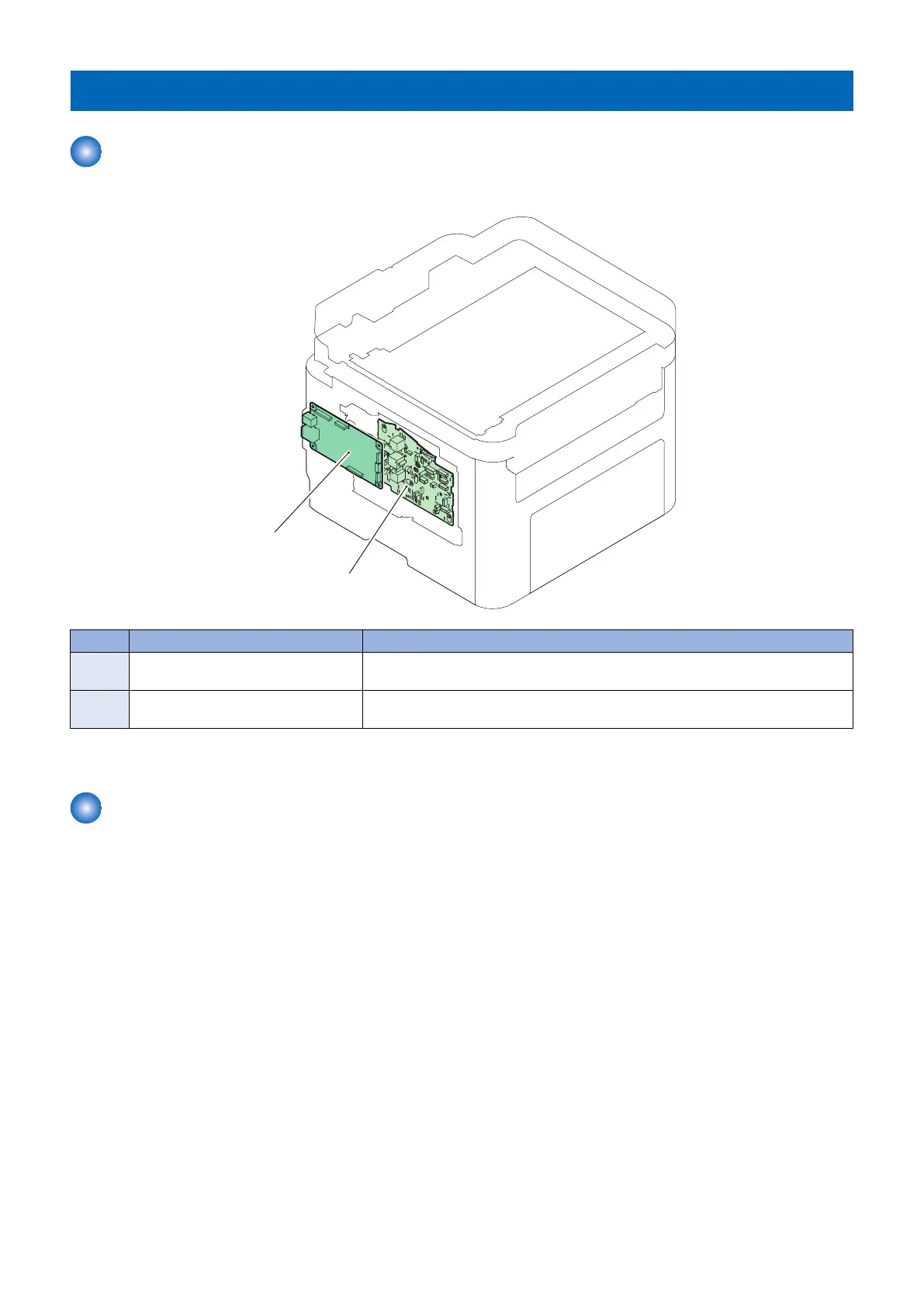
This machine is controlled by the Main Controller and the Engine Controller.
No. Name Role
UNIT1 Engine Controller PCB *1 Printer control, laser control, high voltage control, various I/O control, and retaining
setting values
UNIT2 Main Controller PCB System control, image processing control, network control, and retaining various
setting values
*1: The Engine Controller PCB consists of the High- voltage Power Supply PCB and the DC Controller PCB.
Main Controller PCB
Main controller receives the printing information from the external devices (computer etc.) through interface cables.
This information consists of 2 types of data which includes command data to handle the printer status and the machine specific
information, and data to be printed.
The main controller receives the data to be printed, and creates the video data and send it to the engine controller.
Command data is used for checking the printer status through the interface from external devices.
When the main controller receives this data, it communicates with the engine controller and sends the printer status to the external
devices.
2. Technology
31