Do you have a question about the Canon iR3570 Series and is the answer not in the manual?
| Print Technology | Laser |
|---|---|
| Copy Resolution | 600 x 600 dpi |
| Maximum Original Size | A3 |
| Print Speed | 35 ppm |
| Scan Resolution | 600 x 600 dpi |
| Duplex Printing | Yes |
| Network Connectivity | Ethernet |
| Functions | Print, Copy, Scan |
| Warm-Up Time | 30 seconds or less |
| Memory | 128 MB |
| Interface | Ethernet |
| Operating System Compatibility | Windows, Mac |
| Copy Speed | 35 cpm |
| Paper Sources | 50-sheet stack bypass |
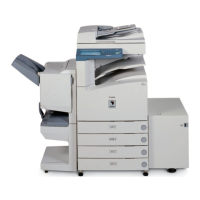
Covers the overall structure and configurations of the system with various accessories.
Details the technical specifications and components of the product.
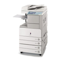
Identifies and labels various components of the machine.
Provides instructions on basic operation and controls.
Lists and describes various settings configurable by the user.
Provides guidance for routine maintenance tasks that users can perform.
Covers crucial safety information for operating the machine.
Lists the technical specifications of the product.
Lists the various functions and capabilities of the machine.
Outlines necessary checks before proceeding with installation.
Details the process of unpacking and installing the machine.
Explains how to verify network connectivity.
Provides solutions for common network issues.
Guides on verifying image quality and machine operations.
Explains how to install the card reader.
Explains the installation process for the NE controller.
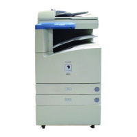
Describes the basic construction and organization of the machine.
Explains the fundamental operational sequences of the machine.
Describes the construction and mechanisms of the main controller.
Describes the electrical components and circuitry.
Outlines the process the machine goes through when starting up.
Explains the procedure for safely shutting down the machine.
Describes how the machine processes images.
Illustrates the path of image data through the machine.
Guides on how to replace various machine parts.
Describes the basic construction of the original exposure system.
Explains the fundamental operational sequences of the system.
Covers various control mechanisms within the system.
Guides on how to replace various machine parts.
Describes the basic construction of the laser exposure system.
Explains the fundamental operational sequences of the laser system.
Covers various control mechanisms within the laser system.
Guides on how to replace various parts of the laser scanner unit.
Describes the basic construction of the image formation system.
Explains the process of image formation.
Explains the fundamental operational sequences.
Describes mechanisms to stabilize image output.
Covers the drum unit and its components.
Covers the drum cleaner unit.
Covers the developing unit and its functions.
Covers the toner cartridge and its function.
Covers the transfer unit and its components.
Covers the transfer mechanism.
Covers the cleaning of the photosensitive drum.
Guides on how to replace various parts related to image formation.
Describes the basic construction of the pickup/feeding system.
Explains the fundamental operational sequences.
Covers the detection of paper jams.
Covers the cassette pick-up unit.
Covers the manual feed pickup unit.
Covers the registration unit.
Covers the duplex feeding unit.
Guides on how to replace various parts of the pickup/feeding system.
Describes the basic construction of the fixing system.
Explains the fundamental operational sequences of the fixing system.
Covers various control mechanisms within the fixing system.
Covers protective mechanisms within the fixing system.
Guides on how to replace various parts of the fixing system.
Describes the control panel and its functions.
Covers the machine's various counters.
Covers the cooling fans used in the machine.
Describes the machine's power supply system.
Guides on how to replace various components related to external controls.
Provides an overview of the MEAP platform.
Covers the MEAP counter mechanism.
Describes the construction of the MEAP platform.
Lists parts that require periodic replacement.
Lists durable parts and consumables.
Outlines the basic procedure for scheduled servicing.
Covers cleaning procedures for various machine parts.
Covers adjustments related to image quality and position.
Covers adjustments related to the scanning system.
Covers adjustments related to the laser exposure system.
Covers adjustments related to the image formation system.
Covers adjustments related to electrical components.
Covers adjustments related to the pickup/feeding system.
Outlines initial checks before troubleshooting image faults.
Provides troubleshooting steps for various issues.
Provides an overview of the machine's electrical components.
Lists all error codes and their descriptions.
Provides detailed explanations for error codes.
Covers error codes related to SEND functions.
Lists jam codes for different parts of the machine.
Lists alarm codes and their causes/remedies.
Covers error codes specific to finishers and saddle finishers.
Covers error codes specific to the DADF.
Provides an overview of the service mode.
Covers the display functions within service mode.
Covers Input/Output display mode.
Covers adjustment settings within service mode.
Covers functions within service mode.
Covers machine settings options.
Covers test print modes.
Covers counter modes.
Lists special tools required for servicing.
Lists oils and solvents used in servicing.