EasyManua.ls Logo

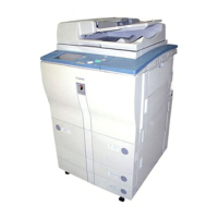
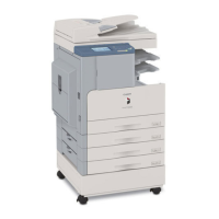
Canon iR8500 User Manual

Canon iR8500
813 pages
To Next Page IconTo Next Page
Page #1 background imageLoading...
Page #1 background image
FY8-13H3-010
iR8500/7200
REVISION 1
AUG. 2001
COPYRIGHT
©
2001 CANON INC. 2000 2000 2000 2000 CANON iR8500/7200 REV.1 AUG. 2001 PRINTED IN JAPAN (IMPRIME AU JAPON)

Table of Contents

Other manuals for Canon iR8500

Questions and Answers:

Canon iR8500 Specifications

General IconGeneral
Print Resolution1200 x 1200 dpi
Copy Resolution600 x 600 dpi
Scan Resolution600 x 600 dpi
Grayscale Halftones256 Levels
DuplexingYes
FunctionsPrint, Copy, Scan
Maximum Original Size11" x 17"
Copy Size11 x 17 inches
ConnectivityUSB, Ethernet
Operating System CompatibilityWindows, Mac
Supported Media SizesLetter, Legal

Summary

CHAPTER 1 INTRODUCTION

1 Features

Overview of the iR8500/7200 series' key features, including speed, durability, and processing capabilities.

2 Specifications

Detailed technical specifications for the iR8500 and iR7200 copiers, covering type, methods, functions, and other parameters.

4 Using the Machine

Instructions on operating the machine, including power switch functions, control panel usage, special features, and user modes.

CHAPTER 2 NEW FUNCTIONS

2 Original Exposure System (iR8500)

Details on the enhanced original exposure system in the iR8500, including changes from previous models and key components.

6 Laser Exposure System

Explanation of the laser exposure system, its components, and basic construction for image formation.

9 Fixing System

Information on the fixing system, including major changes, components, and temperature control mechanisms.

CHAPTER 3 MAIN CONTROLLER

1 Basic Operation

Overview of the main controller's basic operation, functional construction, and electrical circuit.

2 Digital image Processing

Explanation of the digital image processing mechanisms, including input and output processing.

4 Controlling the Power Supply

Details on the machine's power supply modes, including standby, power save, low-power, sleep, and off modes.

CHAPTER 4 INSTALLATION

1 Selecting the Site

Requirements for selecting an appropriate installation site, considering power, environment, and space for operation.

2 Unpacking and Installation (iR8500 Series)

Procedures and important points for unpacking and installing the iR8500 series.

3 Unpacking and Installation (iR7200 Series)

Procedures and important points for unpacking and installing the iR7200 series machine.

CHAPTER 5 MAINTENANCE AND INSPECTION

1 Periodically Replaced Parts

List of parts that require periodic replacement to maintain machine performance, including parts numbers and life estimates.

3 Scheduled Servicing Work

Guidelines and procedures for performing scheduled maintenance tasks on the machine.

4 Scheduled Service Chart

A chart outlining the recommended servicing intervals for various machine components.

CHAPTER 6 TROUBLESHOOTING

1 Guide to the Troubleshooting Tables

Instructions on how to effectively use the troubleshooting tables, including understanding flow charts and codes.

2 Standards and Adjustments

Information on adjusting various image parameters to meet specific standards and ensure optimal output quality.

3 Troubleshooting Faulty Images

Guidance on identifying and resolving common image quality issues such as fogging and uneven density.

4 Troubleshooting Malfunctions

Detailed troubleshooting steps for various error codes (E000-E830) related to machine malfunctions.

APPENDIX

1 GENERAL TIMING CHART

A comprehensive chart illustrating the timing of operations for various machine components during different modes.

3 GENERAL CIRCUIT DIAGRAM

A detailed circuit diagram illustrating the electrical connections between major PCBs and components of the machine.

SERVICE MODE

1 Construction of Service Mode

Explanation of the three-level structure of the service mode screens: Initial, Level 1/2, and Level 3 items.

2 COPIER

Access to service functions related to the copier, including display, I/O, adjustments, and functions.

ERROR CODE

1 Error Codes

Overview of error codes, their classification, and general procedures for handling detected errors.

E000

Details for error code E000, including main causes related to thermistor, thermal switch, and DC controller issues.

E400 (Indicated if iR8500)

Troubleshooting steps for error E400 in iR8500, related to ADF communication cable or ADF controller PCB faults.

E601

Troubleshooting information for error E601, indicating potential issues with wiring, hard disk, or controller PCBs.

Related product manuals