COPYRIGHT
©
2001 CANON INC. 2000 2000 2000 2000 CANON iR8500/7200 REV.1 AUG. 2001
CHAPTER 6 TROUBLESHOOTING
6-4
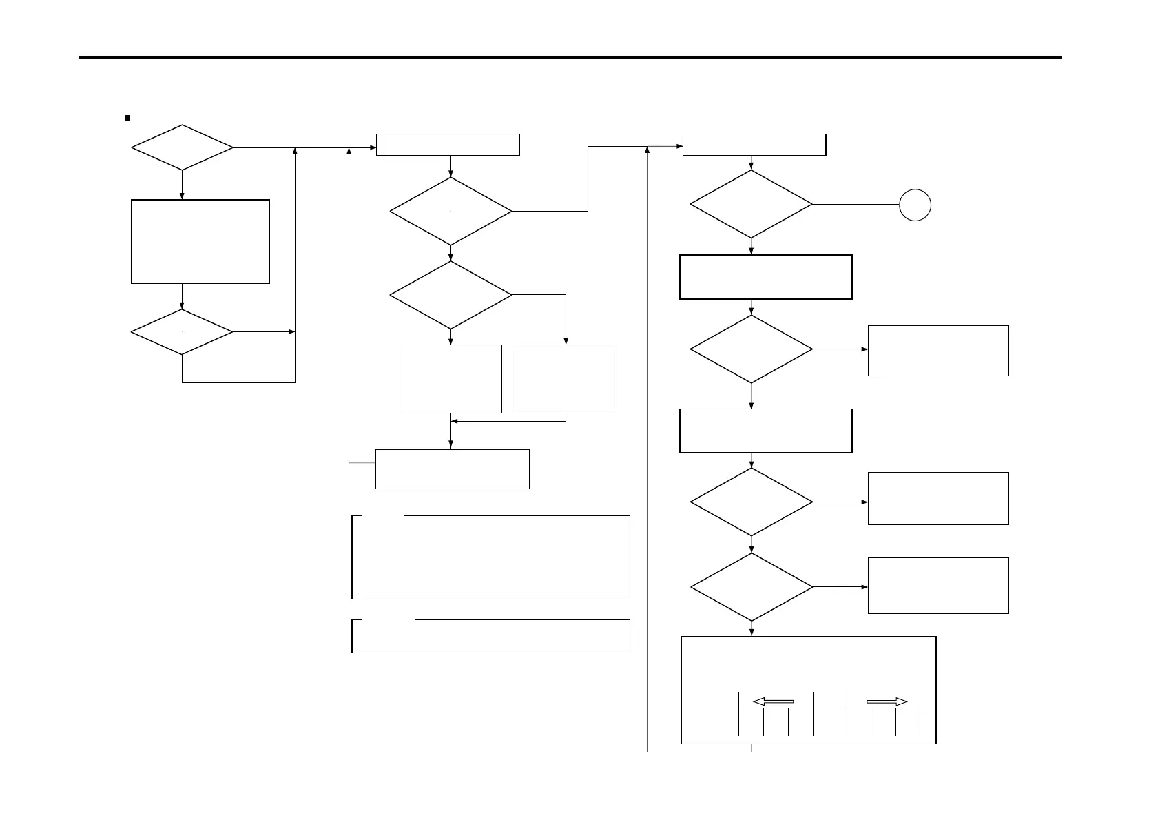
1.1.2 Making Checks on the Printer Side (1/2)
F06-101-02
Is there a
difference in density
between front
and rear?
Is the rear
lighter?
Turn the adjusting
screw at the front of
the primary charging
assembly counter-
clockwise (2 turns
max.).
Turn the adjusting
screw at the rear of
the primary charging
assembly counter-
clockwise (2 max.).
Turn off and then on the power
switch, and generate a single test
print using PG7 or PG4.
1. If there still is a difference in density after giving the adjusting
screw 2 turns on one side (each turn causing a change of
about 0.7 mm), check the charging assembly, scanning lamp,
and scanner for dirt.
2. When turning the adjusting screw counterclockwise, take care
so that the distance between the wire and the grid is not less
than 7.5 mm.
Is the output
free of a fuzzy image
and the density
appropriate?
Is the test print PG6
(solid white) foggy?
Is the reading of
‘VDM’ between 360
and 420?
Is the reading
of ‘VL1M’ between
50 and 90?
Check the following of the
developing assembly system:
1. Developing bias
2. Sleeve for toner coating
<Checking the Density Slope>
<Checking the Solid Black Density>
YES
NO
YES
NO
YES
NO
NO
YES
NO
YES
YES
NO
Is there a
horizontal line in
the image?
Is there a
horizontal line in
the image?
<Checking the Images>
Using PG4, PG7, and PG8
YES
YES
NO
NO
Execute potential
control.
Check the image using PG4.
Check PG8 (solid black).
Caution:
Moving the wire away from the wire makes the image darker,
while bringing it closer makes the image lighter.
Reference:
Make the following selections in
service mode:
COPIER>DISPLAY>DPOT>VDM.
Make the following selections in
service mode:
COPIER>DISPLAY>DPOT>VL1M.
A
Clean the following, and check
them for adhesion of foreign
matter:
[1] Dust-proofing glass
[2] Charging assemblies
[3] Developing cylinder
Check the following; if faulty,
replace it:
1. Laser output
2. Potential control system
Check the primary charging
system and the potential control
system; if normal, replace the
photosensitive drum.
Perform the following:
1. Vary the settings of the following with reference to
the following table: ADJUST>V-CONT>VD-OFST and
ADJUST>V-CONT>VL-OFST:
VD-OFST -4 -3 -2 0 +2 +3 +4
VL-OFST +4 +3 +2 0 -2 -3 -4
Default
Lighter images
Darker images

 Loading...


