Do you have a question about the Canon IR1600 and is the answer not in the manual?
Explains symbols used to indicate special information in the manual.
Describes the structure and contents of the service manual chapters.
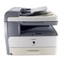
Identifies and illustrates the external and internal parts of the copier.
Details the layout and functions of the machine's control panel keys and indicators.
Covers essential safety precautions, laser light safety, and CDRH requirements.
Explains the indirect photoelectronic reproduction method and its construction.
Divides the machine into six functional blocks for system understanding.
Details the major PCBs and their functions controlling the machine's mechanisms.
Details the image processing and correction steps performed in copier mode.
Provides instructions for disassembling and assembling key components of the system.
Details the circuit used to drive the semiconductor laser according to video signals.
Provides instructions for disassembling and assembling the laser/scanner unit.
Explains the control of the primary charging roller bias for consistent charging.
Describes the toner level sensor and its detection process.
Explains the control mechanisms for paper pickup from cassettes and multifeeder trays.
Details the sensors and procedures for detecting paper jams in various locations.
Explains how the fixing temperature is controlled based on operating conditions and paper type.
Provides instructions for disassembling and assembling parts of the fixing assembly.
Details the construction and circuitry of the machine's control panel.
Explains the power supply PCB, its output voltages, and associated components.
Details the pickup control system for the cassette unit.
Provides instructions for disassembling and assembling the cassette unit.
Explains how paper is delivered to the No. 2 delivery slot and monitored.
Provides instructions for disassembling and assembling the inner 2-way tray unit.
Outlines the environmental and spatial requirements for machine installation.
Provides guidelines for unpacking and installing the machine, including safety notes.
Guides through data initialization using service mode for proper machine setup.
Provides instructions for installing the optional card reader accessory.
Details the installation procedure for the optional image RAM module.
Lists parts that require periodic replacement to maintain machine performance.
Recommends basic service procedures to ensure a longer product life.
Outlines cleaning procedures for specific parts to be performed during user visits.
Provides critical guidelines for storing and handling the drum unit to prevent damage.
Guides through basic adjustments for image quality issues like density and alignment.
Provides systematic steps to diagnose and resolve image and operational faults.
Lists common malfunctions and provides step-by-step solutions.
Explains how to access and use the machine's service mode for advanced settings.
Details various test modes for diagnosing hardware and software functions.
Explains methods for upgrading machine or accessory firmware via PC or ROM replacement.
Provides instructions for downloading firmware updates using a PC and service tools.
Lists prerequisites and software/hardware requirements for firmware downloading.
Details the process of installing system software and finisher firmware.
Guides on connecting to a PC and downloading system software via USB.
Explains the procedure for downloading firmware to the Finisher-L1 accessory.
Provides timing charts illustrating the sequence of operation for various machine functions.
Presents a comprehensive circuit diagram of the machine's electrical components.
Lists special tools required for servicing the machine, along with their uses and ranks.
Details recommended solvents and lubricants for cleaning and maintenance tasks.
Introduces the Printer Board-N1 and Ethernet Network Interface Adapter iN-E5.
Details the specifications for Printer Board-N1, Ethernet Adapter iN-E5, and Hard Disk HD-65.
Explains how to configure network settings and printer settings through user mode.
Guides on configuring network settings via user mode, system settings, and network settings.
Describes how to make printer settings from the control panel or PC driver.
Details the functional blocks of the printer board: CPU, ASIC, DRAM, ROM, and EEPROM.
Explains how to upgrade the printer board by mounting a ROM DIMM.
Provides general instructions for disassembling and assembling the printer board components.
Details the procedure for removing the Hard Disk HD-65.
Explains how to remove the Ethernet Network Interface Adapter iN-E5.
Guides on how to remove the Printer Board-N1 from the machine.
Provides a step-by-step guide for installing the Printer Board-N1.
Details the procedure for installing the Hard Disk HD-65 onto the printer board.
Guides on the installation procedure for the Ethernet Network Interface Adapter iN-E5.
Explains how to access and use the service mode for printer board settings and diagnostics.
Describes the printer board's self-diagnostic program for hardware checks.
Lists warning messages and the actions to take for each.
Details normal error indications and corrective actions.
Lists service call error messages and their corresponding troubleshooting steps.
| Print Technology | Laser |
|---|---|
| Type | Monochrome |
| Maximum Print Resolution | 600 x 600 dpi |
| Print Resolution | 600 x 600 dpi |
| Copy Resolution | 600 x 600 dpi |
| Standard Paper Capacity | 250 sheets |
| Maximum Paper Size | A4 |
| Functions | Print, Copy, Scan |
| Print Speed | 16 ppm |
| Copy Speed | 16 cpm |
| Scan Resolution | 600 x 600 dpi |
| Operating System Compatibility | Windows |
| Interface | USB 2.0 |