CHAPTER 2 STANDARDS AND ADJUSTMENTS
2-2
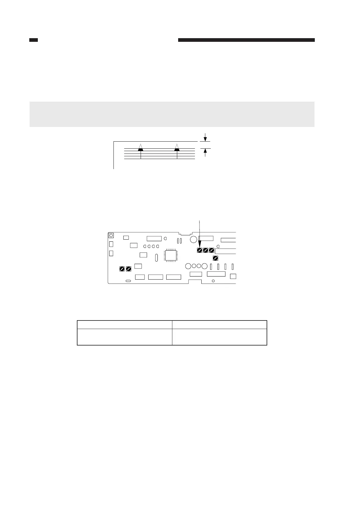
b. Image Leading Edge Margin (registration activation timing)
Make adjustments so that the leading edge margin is 2.5 ±1.5 mm when the Test Sheet is
copied.
Caution:
Be sure to check that the leading edge non-image width is as indicated before performing this
adjustment.
Figure 2-3
1) Turn VR104 on the DC controller PCB so that the margin is as indicated.
Figure 2-4
Table 2-2
Direction of VR104
Clockwise
Counterclockwise
Image leading edge margin
Increases
Decreases
Turing VR104 and Image Leading Edge Margin
2.5 ± 1.5mm
VR104
J102
J101
J107
J101J131
VR103VR102
J103
J130
J114
J104
J105
J109
J106
J102
VR104VR105VR106
VR107