CHAPTER 2 STANDARDS AND ADJUSTMENTS
2-35
Example:
If L4 is 13 mm,
You must shift the original stop position toward the leading edge by 3 mm.
1) Place a sheet of A4 or LTR white copy paper on the original tray.
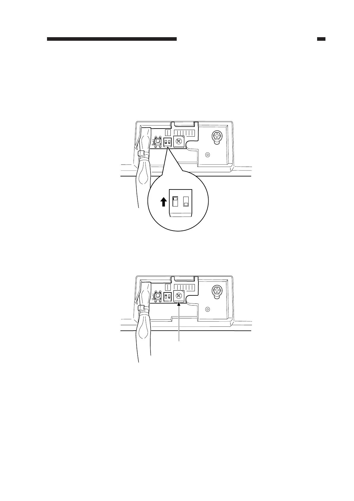
2) Shift bit 1 of the DIP switch (SW1) on the ADF controller PCB to ON; then, push the push
switch (PSW) to pick up the copy paper.
Figure 2-60
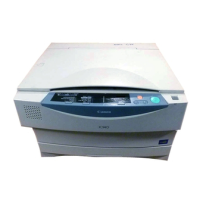
3) Turn the rotary switch (SW2) on the ADF controller PCB clockwise by 10 notches.
Figure 2-61
0
F
E
D
C
B
A
9
8
7
6
5
4
3
2
1
ON
12
ON
12
SW1
0
F
E
D
C
B
A
9
7
6
5
4
3
2
1
ON
12
SW2
8