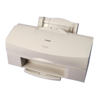
Do you have a question about the Canon QY8-1360-000 and is the answer not in the manual?
Identifies printer components that pose a risk of entanglement during operation.
Warnings about electrical shock hazards when the printer is connected to power.
Caution about the hot metal plate on the BJ cartridge during and after printing.
Guidelines for safely unpacking, handling, and protecting BJ cartridges.
Precautions to prevent nozzle clogging and damage to BJ cartridges.
Proper procedures for turning the printer on and off to protect cartridges.
Guidelines for handling ink tanks to prevent clogging and ensure proper function.
Methods to prevent ink tank ink outlets from clogging.
Warning about static electricity damaging components and altering characteristics.
Procedures to prevent ink leakage and nozzle dry-out during power off.
Information on EEPROM storage and precautions during servicing, including reset procedures.
Notes on using printer driver functions intended for service personnel only.
Precautions for safely handling the printer's power supply components.
Detailed precautions and parts to avoid when dealing with static electricity.
Explains the printer's self-diagnosis feature for detecting hardware defects.
Technical specifications for the BJC-7100 printer.
Technical details of the printer's interface, including modes and signal levels.
IO signal pin configuration for Compatible, Nibble, and ECP modes.
IO signal pin configuration for Nibble mode.
IO signal pin configuration for ECP mode.
Explanation of signals in Compatible Mode, Nibble Mode, and ECP Mode.
Step-by-step instructions for setting up the printer.
Guidelines for choosing an optimal and safe location for printer installation.
Step-by-step instructions for installing the printer.
Procedure for connecting the interface cable between the printer and PC.
Steps for connecting the printer's power supply and turning it on.
Detailed instructions for removing protectors and installing BJ cartridges.
Procedure for aligning print heads to ensure print quality and accuracy.
Instructions for replacing ink tanks in color and photo BJ cartridges.
Proper procedure for turning the printer power on and off.
Functions related to printer servicing, error handling, and diagnostics.
Explains how indicators and beepers signal printer errors.
Lists operator-correctable errors and their descriptions.
Lists service-correctable errors, beeper counts, and reference pages.
Explanation of advanced driver settings for service personnel.
Information on EEPROM storage and reset requirements.
Instructions for manual print head cleaning and deep cleaning.
How to perform built-in self-tests, including nozzle check patterns.
How to enter and use the printer's service mode functions.
Procedure to print the final factory test pattern for diagnostics.
Steps for resetting EEPROM data, including waste ink counters.
How to print the contents of the EEPROM for analysis.
Diagram illustrating the printer's internal components and their connections.
Flowchart detailing the printer's initialization sequence upon power-on.
Overview of the printer's IEEE1284 bidirectional parallel interface.
Explanation of printer mechanisms to prevent print head overheating.
Overview of the printer's mechanical components and their structure.
Block diagrams of the drive circuits for BC-60 and BC-61/BC-62e Photo cartridges.
Overview of the printer's electrical system, split into logic and power supply.
Detailed logic block diagram of the printer's main board.
Lists ordinary and special tools required for servicing the printer.
Lists ordinary and special tools required for servicing the printer.
Important notes to consider during disassembly and reassembly.
Instructions on releasing the carriage lock for servicing.
Instructions for replacing waste ink absorbers and resetting EEPROM.
Procedures for adjusting printer settings.
Procedure for checking and adjusting the head gap.
Flowchart for checking and categorizing head gap results.
Procedure for adjusting the head gap using specific tools.
Guides for diagnosing and resolving printer issues.
General cautions to follow before and during troubleshooting.
Diagnostic flowcharts and action steps for resolving printer errors.
Flowchart for diagnosing common printer errors.
Action steps for resolving specific printer errors.
Cause, suspected parts, and measures for print position errors.
Cause and troubleshooting for home position detection errors.
Cause and troubleshooting for purge unit errors.
Cause and troubleshooting for sheet feeder initialization errors.
Cause and troubleshooting for printer temperature errors.
Cause and troubleshooting for waste ink level errors.
Cause and troubleshooting for EEPROM read errors.
Cause and troubleshooting for control ROM read errors.
Schematic diagrams of the printer's electronic circuits.
Schematic diagrams of the printer's electronic circuits.
Circuit diagram for the MPU, memory ICs, and related components.
