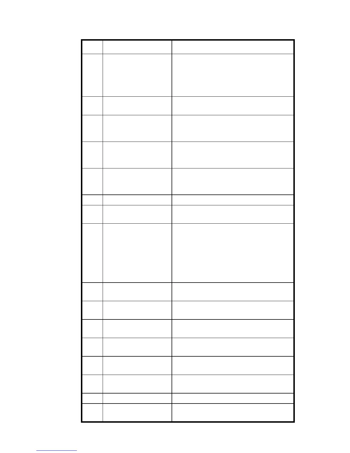
Trailer Jockey Operators Handbook
7
3 Speedometer /
Alphanumeric Display
Indicates vehicle speed in MPH and KPH.
Digital alphanumeric display below
speedometer dial displays additional
information. Refer to XREF for more
information
4 Status LED Panel 2 Multiple LEDs indicate various conditions.
Refer to Figure 2-2 for more information
5 Oil Pressure Gauge Indicates engine oil pressure. Red indicator
light indicates potentially damaging low
pressure.
6 Water Temperature
Gauge
Indicates temperature of engine coolant in
ºF and ºC. Normal reading should be 180 ºF
to 205 ºF.
7 Voltmeter Indicates voltage in electrical system. Low
voltage may indicate problem with battery
and/or alternator.
8 Fuel Gauge Indicates fuel remaining in tank.
9 Air System Pressure
Gauge 1
Indicates pressure in air brake system in
PSI and KPa. Normal reading should be
10 Key Switch Three-position, key-operated switch. In
OFF position, electrical system is de-
energized and key can be removed. In ON
position, the electrical system is energized.
In START position, starter is engaged to
start engine. Release to ON position when
engine is started.
11 Air System Pressure
Gauge 2
Indicates pressure in air brake system in
PSI and KPa. Normal reading should be
12 Windshield Wiper
Control Knob
Turns to activate variable speed wipers.
Push to activate windshield washers.
13 Auxiliary Fan Switch Rocker switch that controls the auxiliary
fan .
14 Mirror Heat Switch Rocker switch that contols the outside rear-
view mirror heaters
15 LH Mirror Motor
Switch
Rocker switch that adjusts the left hand rear
view mirror.
16 RH Mirror Motor
Switch
Rocker switch that adjusts the right hand
rear view mirror.
17 Trailer Brake Lever Activates the trailer brake.
18 Beacon Light Switch Rocker switch that activates the beacon
light.
Table 2-1 Controls & Indicators (Cont.)
Item Name Function