11Instruction manual BU521Please keep this instruction manual for future reference
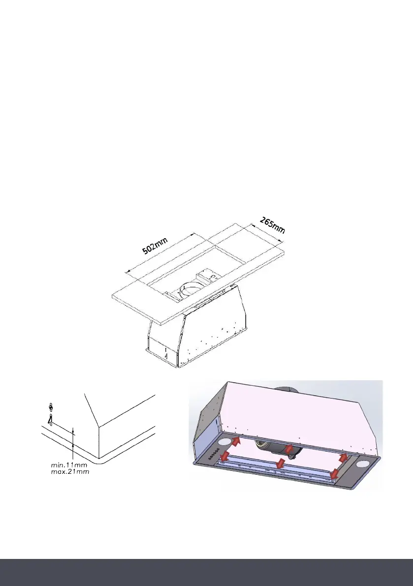
› Make a cut-out in the bottom of the cabinet which is suitable to hold the appliance in
position (Fig.4).
› Prepare the power supply.
› Create a hole for air evacuation.
› Adjust the position of the stop side-springs using the appropriate screws, according to the
thickness of the board the appliance will be fixed to (Fig.5).
› Insert the appliance into the hole made in the cabinet until the stop click of the side springs
is heard and the appliance is locked in position.
› Insert the screws provided into the holes inside the appliance to secure it completely (Fig.6).
› Make a cut-out in the bottom of the cabinet which is suitable to
hold the appliance in position (Fig.4).
› Prepare the power supply.
› Create a hole for air evacuation.
› Adjust the position of the stop side-springs using the appropriate
screws, according to the thickness of the board the appliance will
be fixed to (Fig.5).
› Insert the appliance into the hole made in the cabinet until the
stop click of the side springs is heard and the appliance is locked
in position.
› Insert the screws provided into the holes inside the appliance to
secure it completely (Fig.6).
FIG.4
FIG.5
FIG.6
DUCTED VERSION
› Connect the flange to the air evacuation hole with appropriate ducting.
› Connect the appliance to the electrical mains through the supply cord.
R EC I R C ULATING VERSION
› Connect the flange with appropriate ducting to convey the air to the top of the cabinet.
› Connect the appliance to the electrical mains through the supply cord.
W ARNING:
Before connecting the flexible exhausting pipe to the motor, make sure the stop valve, which is on the air outlet of the motor,
can open and close freely.
› Make a cut-out in the bottom of the cabinet which is suitable to
hold the appliance in position (Fig.4).
› Prepare the power supply.
› Create a hole for air evacuation.
› Adjust the position of the stop side-springs using the appropriate
screws, according to the thickness of the board the appliance will
be fixed to (Fig.5).
› Insert the appliance into the hole made in the cabinet until the
stop click of the side springs is heard and the appliance is locked
in position.
› Insert the screws provided into the holes inside the appliance to
secure it completely (Fig.6).
FIG.4
FIG.5
FIG.6
DUCTED VERSION
› Connect the flange to the air evacuation hole with appropriate ducting.
› Connect the appliance to the electrical mains through the supply cord.
R EC I RC ULATING VERSION
› Connect the flange with appropriate ducting to convey the air to the top of the cabinet.
› Connect the appliance to the electrical mains through the supply cord.
W ARNING:
Before connecting the flexible exhausting pipe to the motor, make sure the stop valve, which is on the air outlet of the motor,
can open and close freely.
WARNING:
Before connecting the flexible exhausting pipe to the motor, make sure the stop valve, which is
on the air outlet of the motor, can open and close freely.
FIG 4
FIG 5 FIG 6
 Loading...