15Instruction manual C706GPlease keep this instruction manual for future reference
› The room must also allow for the influx of the air needed for proper combustion. The flow of
air for combustion purposes must, not be less than 2m³/h per kW of installed capacity. The
supply of said air can be effected by means of direct influx from the outside through a duct
with an inner cross section of at least 100cm² which must not be able to be accidentally
blocked.
› Intensive and prolonged use of the appliance may necessitate supplemental ventilation, e.g.
opening a window or increasing the power of the air intake system (if present).
› Liquefied petroleum gases are heavier than air and, as a result, settle downwards. Rooms in
which LPG tanks are installed must be fitted with ventilation openings to the outside in order
to allow the gas to escape in the event of a leak. Therefore, LPG tanks, whether empty or
partially full, must not be installed or stored in rooms or spaces below ground level (cellars,
ect.). It is also a good idea to keep only the tank currently being used in the room, making sure
that it is not near sources of heat (ovens, fireplaces, stoves, etc.) that could raise the internal
temperature of the tank above 50ºC.
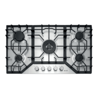
GAS HOB INSTALLATION
The gas hobs are prepared with protection degree against excessive heating of type X, the
appliance can therefore be installed next to cabinets, provided the height does not exceed that of
the hob. For a correct installation of the cooking hob the following precautions must be followed:
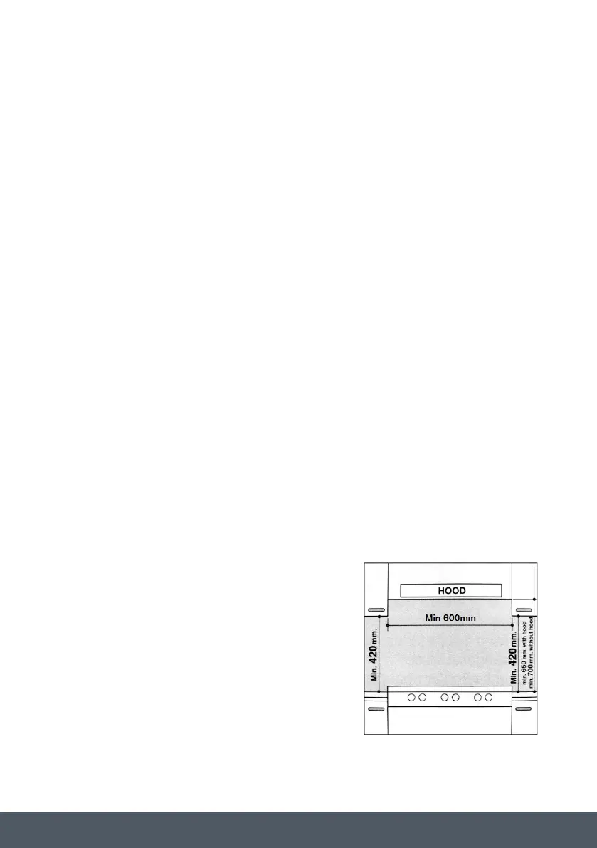
› The hob may be located in a kitchen, a kitchen/diner or
bed sitting room, but not in a bathroom or shower room.
› The furniture standing next to the hob, that is higher than
the worktop, must be placed at least 110mm from the
edge of the hob.
› The cabinets positioned next to the hood should be at a
height of at least 420mm (Fig. 5).
Fig.5 Fig.6
d) Should the hob be installed directly under a cupboard, the cupboard should be at least 700mm from the
worktop, as shown in Fig.5.
e) The cut out dimensions for the worktop must be those indicated in the figures shown below. Fixing hooks
are provided which allow place the hob plate on work tops that measure 20 to 40 mm in thickness (see
Fig. 6).To obtain a of the hob plate it is advisable to use all the fixing supplied.
Fig.6
Hook position for Hook position for Hook position for
H=30mm top H=40mm top H=20mm top
N.B: Use the hook contained in the "accessories set"
In the event the hob is not installed above a built-in oven, a wood panel must be inserted as insulation.
This panel must be placed at least 20 mm from the bottom of the hob itself.
Important: When installing the hob above a built-in oven, the oven should be placed on two wooden strips;
in the case of a joining cabinet surface, remember to leave a space of at least 45 x 560 mm at the back.
FIG.5