19Instruction manual C706GPlease keep this instruction manual for future reference
As the colours of the wires in the mains lead may not correspond with the coloured markings
identifying the terminals in your plug, proceed as follows: Connect the Green & Yellow wire to
terminal marked ‘E’or
● The fuse and electrical system can withstand the load required by the appliance;
● That the electrical supply system is equipped with an efficient earth hook-up according to the norms and
regulations prescribed by law;
● That the plug or switch are easily accessible.
Important: the wires in the mains lead are coloured in accordance with the following code:
Green & Yellow - Earth
Blue - Neutral
Brown - Live
As the colours of the wires in the mains lead may not correspond with the coloured markings identifying the
terminals in your plug, proceed as follows: Connect the Green & Yellow wire to terminal marked "E"
or
or coloured Green or Green & Yellow.
Connect the Brown wire to the terminal marked "L" or coloured Red.
Connect the Blue wire to the terminal marked "N" or coloured Black.
Adapting the hob for Different Types of Gas
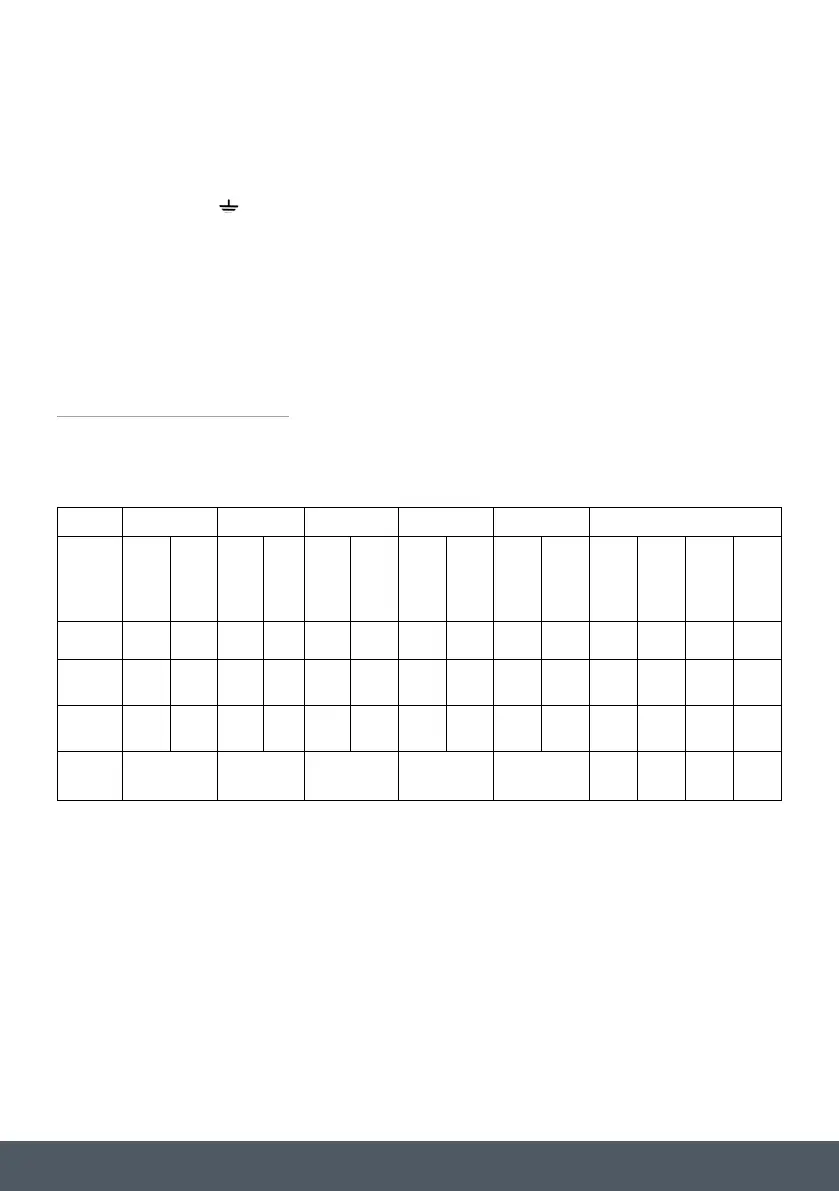
Table1
Burners and Injector Specifications
At 15°C and 1013 mbar-dry gas
P.C.I.G20 37.78 MJ/m³ P.C.I.G25.1 32.51 MJ/m³
P.C.I.G25 32.49 MJ/m³ P.C.I.G27 30.98 MJ/m³
P.C.I.G2.350 27.20MJ/ m³ P.C.I.G30 49.47MJ/Kg
or coloured Green or Green & Yellow.
Connect the Brown wire to the terminal marked “L” or coloured Red.
Connect the Blue wire to the terminal marked “N” or coloured Black.
ADAPTING THE HOB FOR DIFFERENT TYPES OF GAS
BURNERS AND INJECTOR SPECIFICATIONS
● The fuse and electrical system can withstand the load required by the appliance;
● That the electrical supply system is equipped with an efficient earth hook-up according to the norms and
regulations prescribed by law;
● That the plug or switch are easily accessible.
Important: the wires in the mains lead are coloured in accordance with the following code:
Green & Yellow - Earth
Blue - Neutral
Brown - Live
As the colours of the wires in the mains lead may not correspond with the coloured markings identifying the
terminals in your plug, proceed as follows: Connect the Green & Yellow wire to terminal marked "E"
or
or coloured Green or Green & Yellow.
Connect the Brown wire to the terminal marked "L" or coloured Red.
Connect the Blue wire to the terminal marked "N" or coloured Black.
Adapting the hob for Different Types of Gas
Table1
Burners and Injector Specifications
G20 (UK)
G25 G25.1 G27 G2.350
G30 (UK)
Burner Thermal
power
(kW)
Injector
1/100
(mm)
Therma
l power
(kW)
Inject
or
1/100
(mm)
Thermal
power
(kW)
Injector
1/100
(mm)
Thermal
power
(kW)
Injector
1/100
(mm)
Thermal
power
(kW)
Injector
1/100
(mm)
Thermal
power
(kW)
Injector
1/100
(mm)
Injector
1/100
(mm)
Injector
1/100
(mm)
Auxiliary
0.90 69 0.90 69 0.90 69 0.90 75 0.90 96 0.90 50 44 43
Semi rapid
1.88 97 1.88 97 1.88 97 1.88 106 1.88 131 1.88 68 64 60
Triple Ring
3.00 131 3.00 131 3.00 131 3.00 136 3.00 165 3.00 86 82 75
Supply
pressures
20mbar 25mbar 25mbar 20mbar 13mbar
30
mbar
36
mbar
50
mbar
At 15°C and 1013 mbar-dry gas
P.C.I.G20 37.78 MJ/m³ P.C.I.G25.1 32.51 MJ/m³
P.C.I.G25 32.49 MJ/m³ P.C.I.G27 30.98 MJ/m³
P.C.I.G2.350 27.20MJ/ m³ P.C.I.G30 49.47MJ/Kg