11Instruction manual TBU850 / TBU520 Please keep this instruction manual for future reference
› Make a cut-out in the bottom of the cabinet of the
following sizes:
TBU520: 265mm x 498mm
TBU850: 265mm x 835mm
Make sure the cabinet structure and the material used
allow you to make this opening without causing any
damage, even during the appliance installation.
› Prepare the power supply.
› Create a hole for air evacuation.
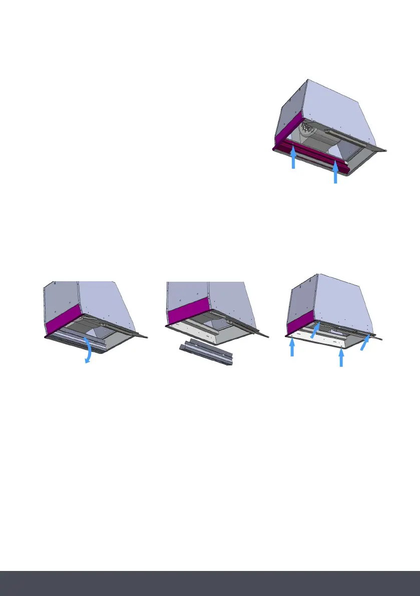
› Remove the fixing screws of the rear steel bar (Fig.5).
› Rotate the steel bar (including the LED bar) to remove it from its position (Fig.6-7).
Electrically disconnect the the LED Bar.
› Make a cut-out in the bottom of the cabinet of the following sizes:
TBU520: 265mm x 498mm
TBU850: 265mm x 835mm
Make sure the cabinet structure and the material used allow you to make
this opening without causing any damage, even during the appliance
installation.
› Prepare the power supply.
› Create a hole for air evacuation.
› Remove the fixing screws of the rear steel bar (Fig.5).
› Rotate the steel bar (including the LED bar) to remove it from its position
(Fig.6-7). Electrically disconnect the the LED Bar.
› Insert the appliance into the hole made in the cabinet and fix it by inserting the screws supplied into the holes (Fig.8).
› Refit the stainless steel bar, electrically connect the LED bar and refit the grease filter.
FIG.5
FIG.6
FIG.7
WARNING:
Before connecting the flexible exhausting pipe to the motor, make sure the stop valve, which is on the air outlet of the motor,
can open and close freely.
DUCTED VERSION
› Connect the flange to the air evacuation hole with appropriate ducting.
› Connect the appliance to the electrical mains through the supply cord.
RECIRCULATING VERSION
› Connect the flange with appropriate ducting to convey the air to the top of the cabinet.
› Connect the appliance to the electrical mains through the supply cord.
FIG.8
› Insert the appliance into the hole made in the cabinet and fix it by inserting the screws
supplied into the holes (Fig.8).
› Refit the stainless steel bar, electrically connect the LED bar and refit the grease filter.
WARNING:
› Before connecting the flexible exhausting pipe to the motor, make sure the stop valve,
which is on the air outlet of the motor, can open and close freely.
 Loading...