Instruction manual WDU060, WDU080 & WDU12520 Please keep this instruction manual for future reference
AIR SWITCH ASSEMBLY INSTRUCTIONS
DISPOSER AIR SWITCH ASSEMBLY IS SUPPLIED IN THREE
BASIC PARTS:
base of the disposer. Only the
connection (5)
nozzle to connect air tube
a
A.
B. (3) through the drilled
endthe Actuator Outlet (3)
end
supplied the
ord
1.
2.
3.
4.
5.
6.
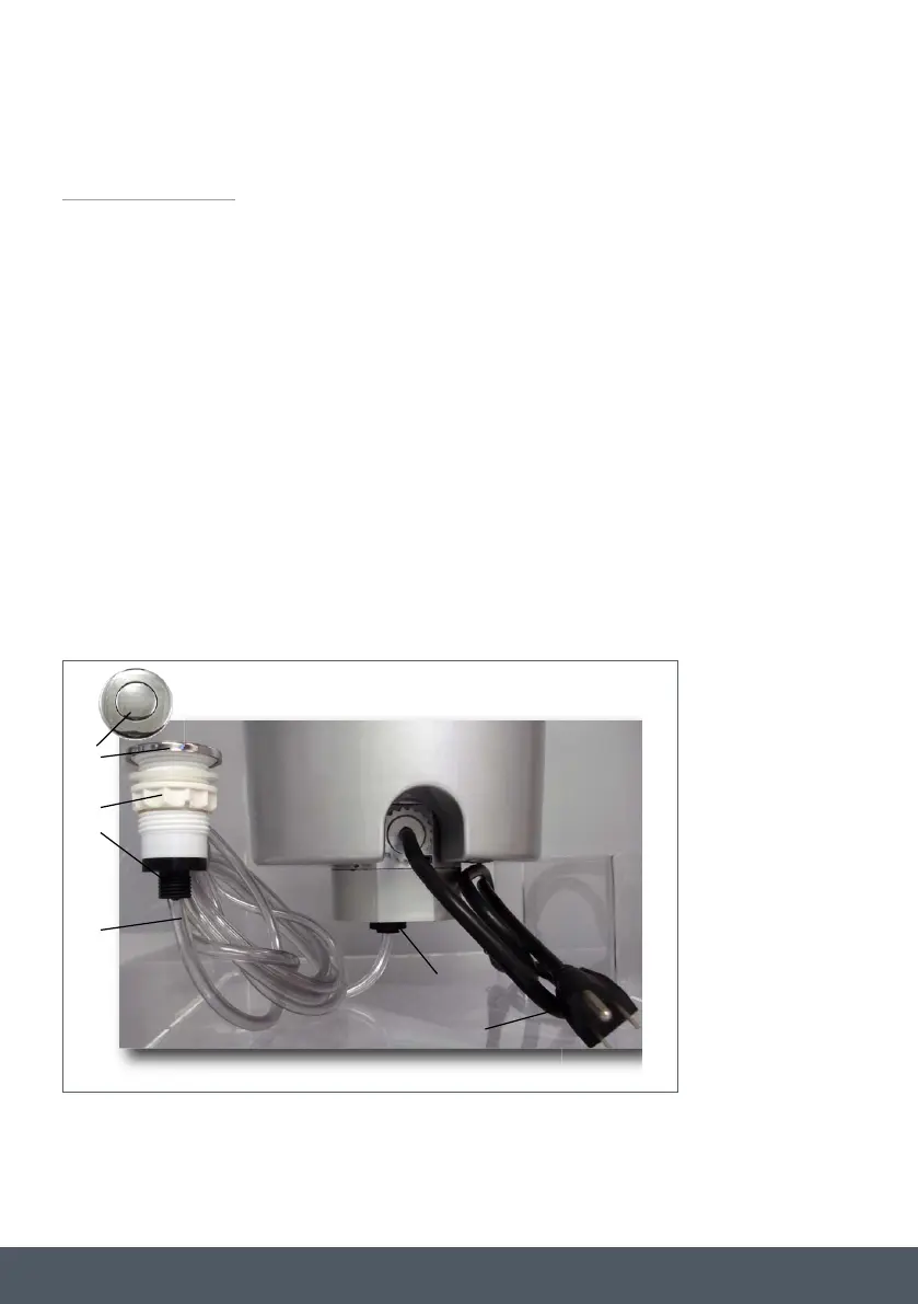
The Actuator which consists of:
1. Actuator Button
2. Actuator Nut
3. Actuator Outlet (Black Threaded portion)
The Air Switch is installed into the base of the
disposer. Only the air tube connection nozzle
(5) is visible from the outside of the disposer.
Air Tube Assembly which consists of:
4. Air Tube-Clear or black
5. Sensor Inlet nozzle to connect air tube
Actuator Image Representational