4 my.carbide3d.com support@carbide3d.com 5
Items Needed in Step 1
Description Qty
Baseframe Members 4
Y-Right Assembly 1
Y-Left Assembly 1
Y-Axis Assembly Hardware: M6×16mm Button Head Cap Screws 16
Tool Bag 1
Cable Track 1
X-Axis Gantry Assembly 1
1.1 Unpack Box 1
1. In Box 1, locate the box labeled Open Me First,
remove the tool bag, and set the box aside.
2. Locate the S5 Electronics and HDZ boxes and
set them aside.
3. Locate the Baseframe box between the two
Y-Rails at the bottom of Box 1 and remove it.
4. Open the Baseframe box and remove the four
baseframe members.
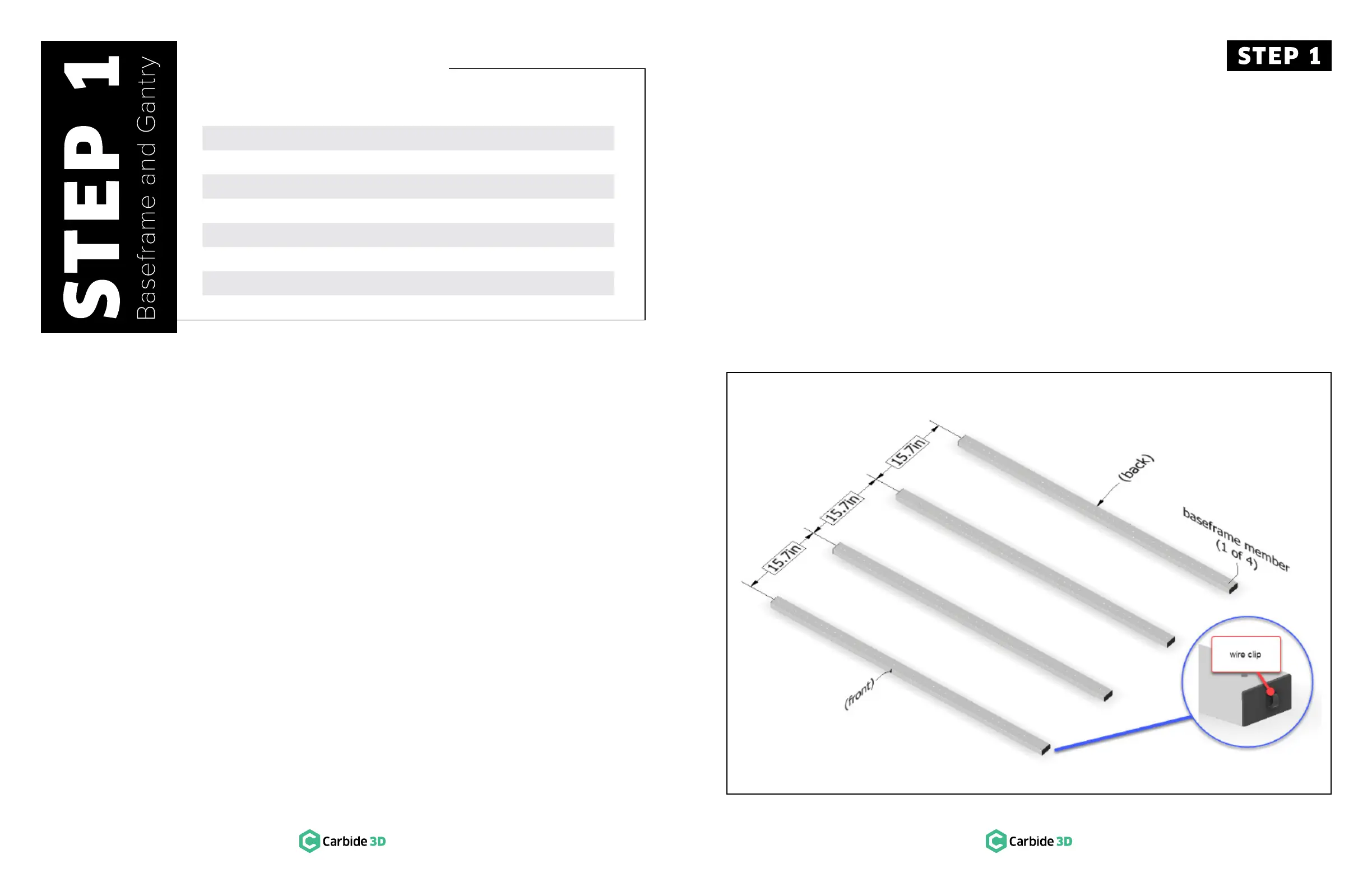
Figure 1-1
1.2 Position Baseframe
1. Position the four baseframe members
horizontally across your table about 15.7 inches
apart, center to center. See Figure 1-1.
a. The wire clips face to the right.
2. Open the wire clip on the end of each
baseframe member.