6 my.carbide3d.com support@carbide3d.com 7
1.3 Install Y-Right Assembly
NOTE: This step is much easier with two people.
The Y-assembly is heavy and can easily tip over if set
upright before attaching it to the baseframe.
1. Locate the Y-Right assembly and the hardware
bag in the bottom of Box 1.
a. Y-Right has a Carbide 3D logo on the front
plate.
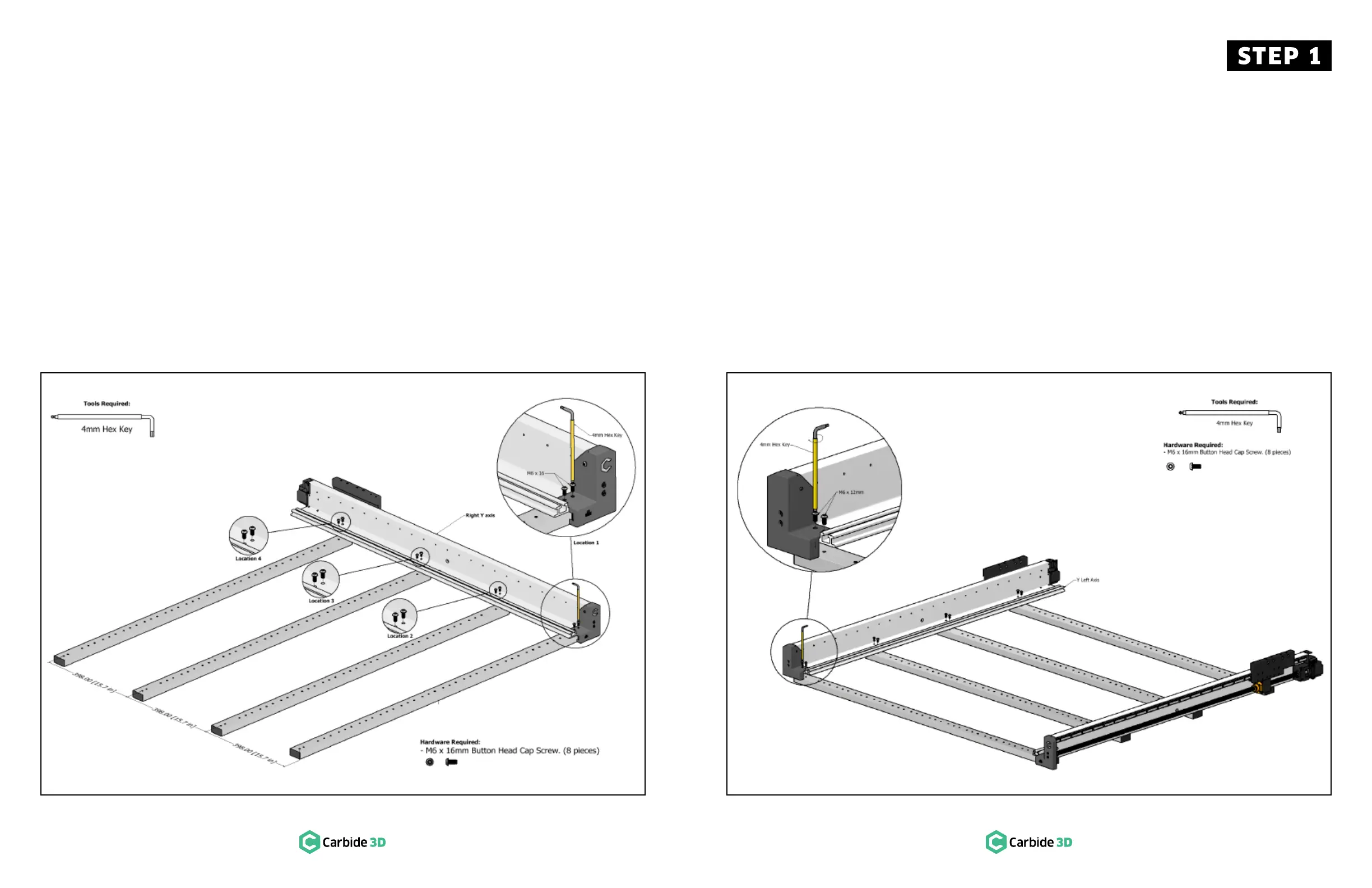
2. Set the Y-Right assembly on the right side of the
baseframe. See Fig. 1-2.
a. Align the front edge with the front edge of
the first baseframe member.
b. Align with the last set of screw holes in each
baseframe member.
Figure 1-2
1.4 Install Y-Left Assembly
NOTE: This step is much easier with two people.
The Y-assembly is heavy and can easily tip over if set
upright before attaching it to the baseframe.
1. Locate the Y-Left assembly in the bottom of
Box1.
a. Y-Left has a blank front plate.
2. Set the Y-Left assembly on the left side of the
baseframe. See Fig. 1-3.
a. Align the front edge with the front edge of
the first baseframe member.
b. Align with the last set of screw holes in each
baseframe member.
Figure 1-3
3. Use a 4mm hex key and eight (8) M6×16mm
BHCS to attach the assembly. See Fig. 1-3.
Snug the screws but don’t fully tighten.
a. Y-Left assembly is attached in four locations.
b. At location 1, the BHCS insert through the
holes in the end cap.
NOTE: Don’t worry about squaring the baseframe
yet.
3. Use a 4mm hex key and eight (8) M6×16mm
BHCS to attach the Y-assembly. See Fig. 1-2.
Snug the screws but don’t fully tighten.
a. Y-Right assembly is attached in four
locations.
b. At location 1, the BHCS insert through the
holes in the end cap.
NOTE: Don’t worry about squaring the baseframe
yet.
 Loading...