support@carbide3d.com docs.carbide3d.com 10/02/2020 Version 1.0
Install the Y-Axis Proximity Switch Mount
Required Components:
Y-Axis Proximity Switch Mount
M5 × 35mm Socket Head Cap Screw
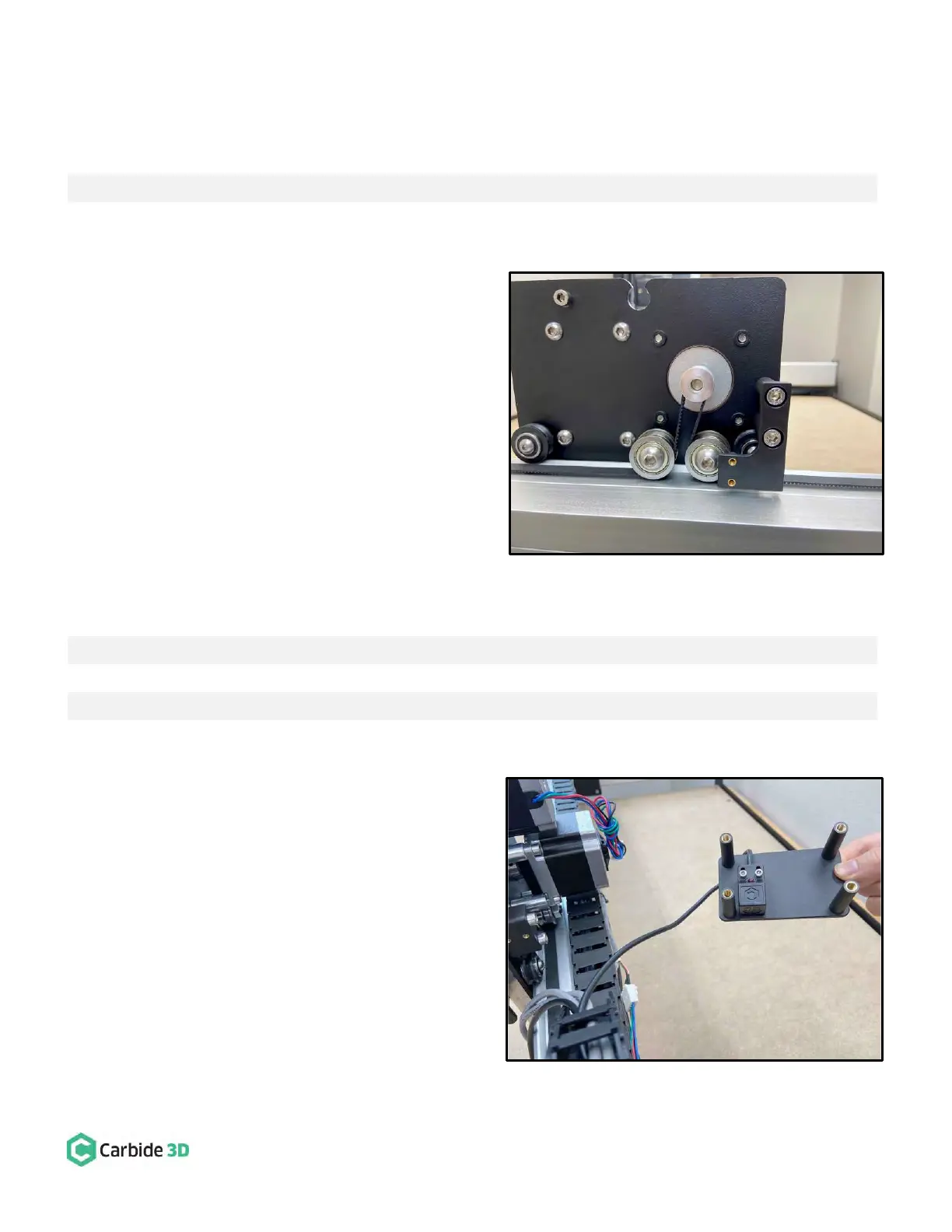
1. Install the Y-Axis proximity switch mount to the
outside of the Y2-carriage. See Fig. 13.
a. Align the mount with the two M5 holes on
the outside of the Y2-carriage and the two
threaded inserts down and to the front.
b. Use a 4mm hex key and two (2)
M5×35mm SHCS to secure.
Install the Z-Axis Proximity Switch and
Mount
Required Components:
Z-Axis Proximity Switch (2675mm XXL, 2350mm XL, and 610mm Shapeoko 3)
M3 × 18mm Socket Head Cap Screw
Z-Axis Proximity Switch Mount
M5 × 10mm Socket Head Cap Screw
1. Install the Z-Axis proximity switch to the back side
of the Z-Axis mount. See Fig. 14.
a. Locate the Z-Axis proximity switch exiting
the drag chain at the X-Axis head bracket.
b. Position the proximity switch with the red
LED facing out and the target pointing
down.
c. Align the proximity switch’s mounting
slots with the two threaded inserts on the
back of the mount.