support@carbide3d.com docs.carbide3d.com 10/02/2020 Version 1.0
Install the Proximity Switches and Mounts
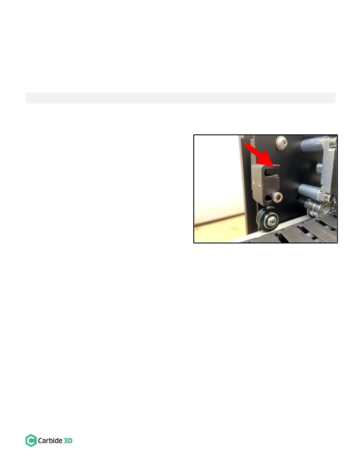
Install the X-Axis Proximity Switch Mount
Required Components:
X-Axis Proximity Switch Mount
M5 × 25mm Socket Head Cap Screw
1. Install the X-Axis proximity switch mount to the
back of the X/Z-carriage. See Fig. 12.
a. Position the proximity switch mount with
the two gold-colored threaded inserts
facing out (away from X-motor) and the
screw head recesses at the end of each
slot facing back (away from the carriage
plate).
b. Align the mounting slots with the two M5
screw holes on the Y2-side of the X-motor.
c. Use a 4mm hex key and two (2)
M5×25mm SHCS to secure.
d. Before tightening, be sure to nestle the
M5 screw heads into the recesses at the
end of each mounting slot.