support@carbide3d.com docs.carbide3d.com 10/02/2020 Version 1.0
Prep and Re-Install the Drag Chain
Install the Proximity Switch Cables
Required Components:
X-Axis Proximity Switch Cable (2675mm XXL and 2350mm XL)
Y-Axis Proximity Switch Cable (2540mm XXL and 2200mm XL)
Z-Axis Proximity Switch Cable (2675mm XXL and 2350mm XL)
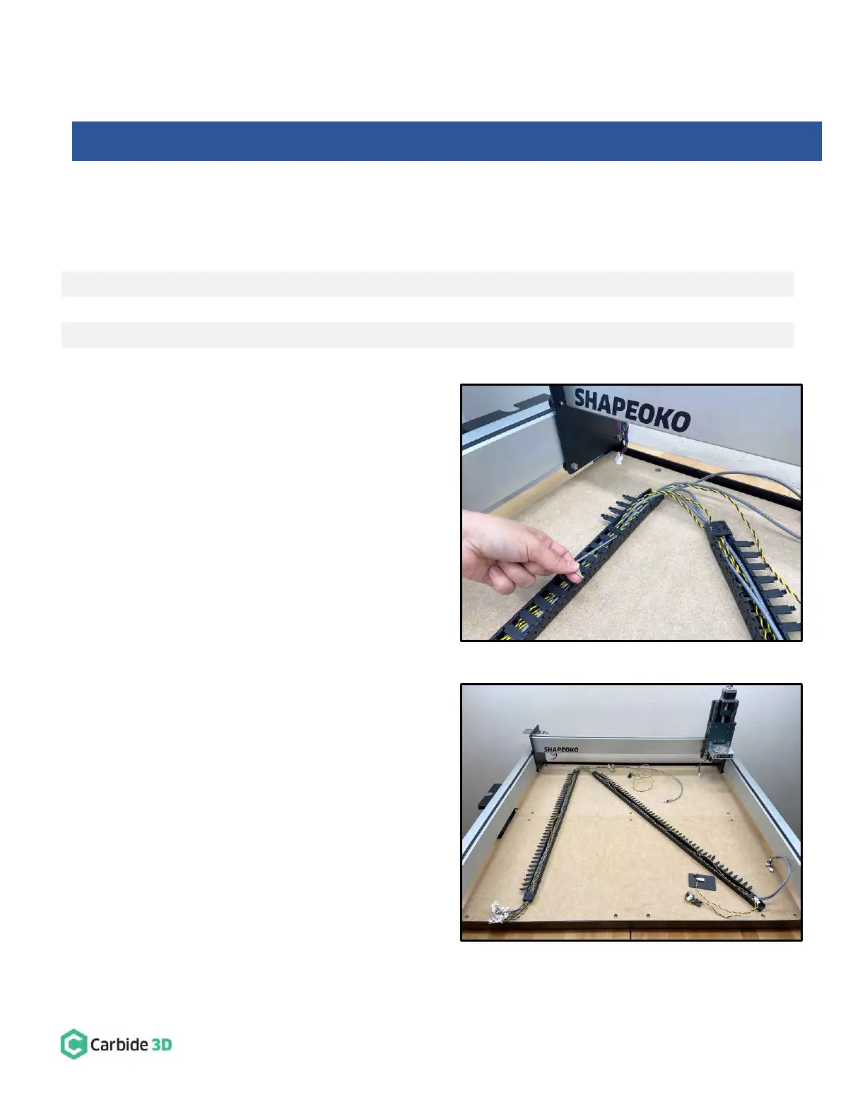
1. Open up the drag chain and remove the three
homing switch cables (black/yellow or
black/orange twisted wires). See Fig. 30 and
Fig. 31.
a. Position the drag chain on the baseframe
as shown in Fig. 31, with the chain’s clip-
on panels facing up. (Only one side of the
chain will open; be sure this side is facing
up.)
b. Use a hex key or screwdriver as a lever to
pry open one side of each drag chain link.
Start from the rear of the machine and
work your way forward as shown in
Fig. 30.
c. Remove the X-, Y-, and Z-Axis homing
switch cables.
2. Label the proximity switches.
a. Identify the X-, Y-, and Z-Axis proximity
switch cables by comparing the length
printed on the switch body with the table
above.
b. Use a permanent marker or piece of tape
to label both ends of each proximity
switch cable.
Shapeoko 3 Machines: Skip ahead to the “Install the Proximity Switches” section on page 35.