EasyManuals Logo

Carbide 3D Shapeoko Proximity Switch Kit User Manual

Default Icon
42 pages
To Next Page IconTo Next Page
To Previous Page IconTo Previous Page
Page #30 background imageLoading...
Page #30 background image
support@carbide3d.com docs.carbide3d.com 10/02/2020 Version 1.0
30
Install the Y-Axis Proximity Switch Mount
Required Components:
Item
Description
Qty
G
Y-Axis Proximity Switch Mount
1
H
M5 × 35mm Socket Head Cap Screw
2
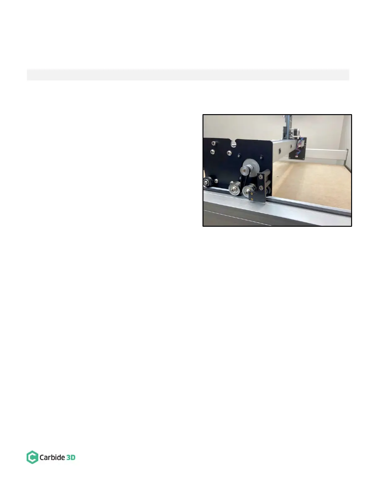
1. Install the Y-Axis proximity switch mount to the
outside of the Y2-carriage. See Fig. 29.
a. Align the mount with the two M5 holes on
the outside of the Y2-carriage, with the
threaded inserts down and to the front.
b. Use a 4mm hex key and two (2)
M5×35mm SHCS to secure.
Figure 29

Questions and Answers:

Question and Answer IconNeed help?

Do you have a question about the Carbide 3D Shapeoko Proximity Switch Kit and is the answer not in the manual?

Carbide 3D Shapeoko Proximity Switch Kit Specifications

General IconGeneral
BrandCarbide 3D
ModelShapeoko Proximity Switch Kit
CategorySwitch
LanguageEnglish