support@carbide3d.com docs.carbide3d.com 10/02/2020 Version 1.0
Install the Proximity Switch Mounts
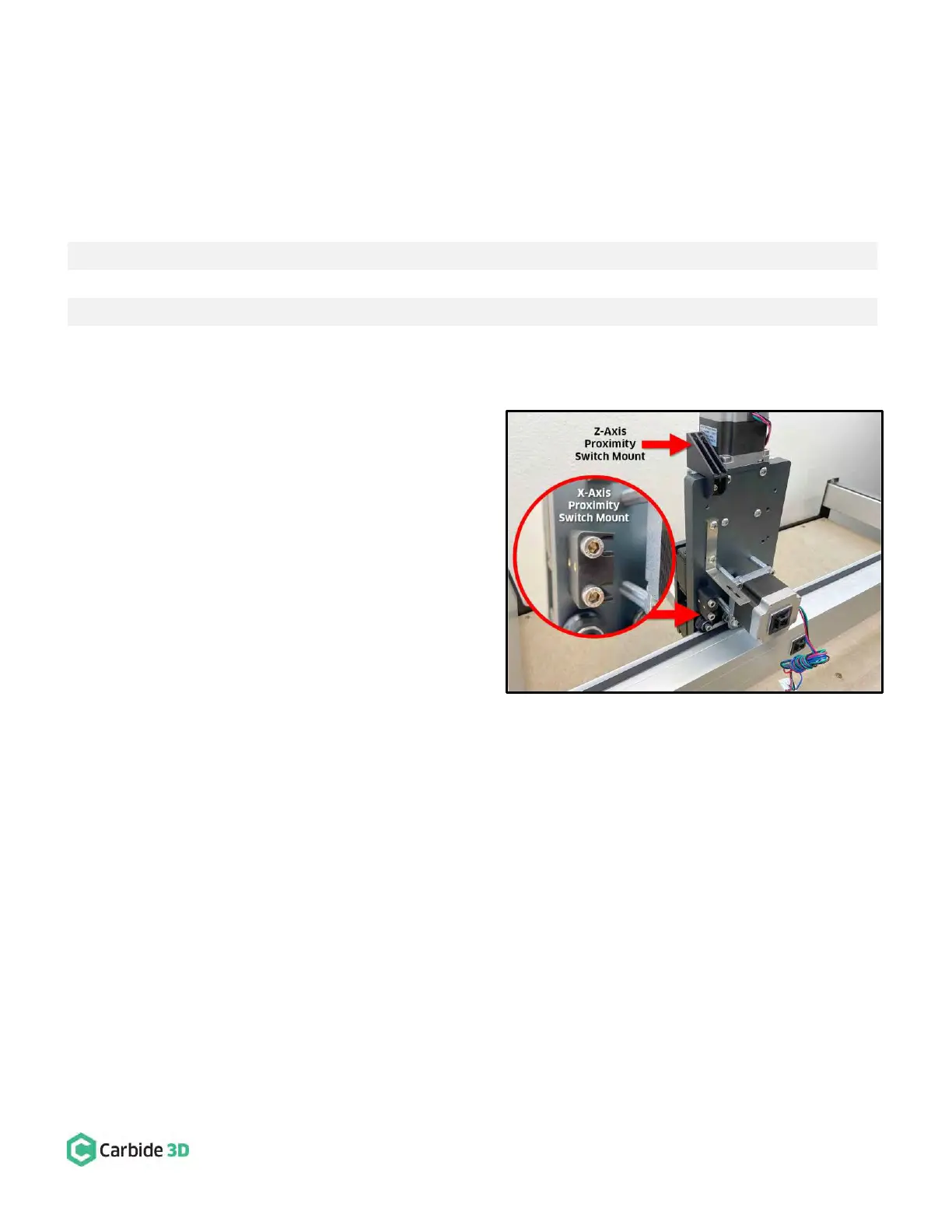
Install the X- and Z-Axis Proximity Switch Mounts
Required Components:
X-Axis Proximity Switch Mount
M5 × 25mm Socket Head Cap Screw
Z-Axis Proximity Switch Mount
M4 × 6mm Button Head Cap Screw
1. Install the X-Axis proximity switch mount to the
back of the HDZ. See Fig. 28 and Fig. 28 inset.
a. Align the mounting slots with the two M5
screw holes on the Y2-side of the X-motor.
b. The two gold-colored threaded inserts on
the mount face out (away from X-motor).
c. Use a 4mm hex key and two (2)
M5×25mm SHCS to secure.
d. Before fully tightening the screws, slide
the mount toward the X-motor far as it
will go.
2. Install the Z-Axis proximity switch mount to the
back of the HDZ. See Fig. 28.
a. Align the mount with the M4 screw hole
at the very top of the HDZ.
b. Use a 2.5mm hex key and one (1) M4×6mm BHCS to secure the mount at the top of the HDZ.