support@carbide3d.com docs.carbide3d.com 10/02/2020 Version 1.0
Remove the Homing Switches and Drag Chain
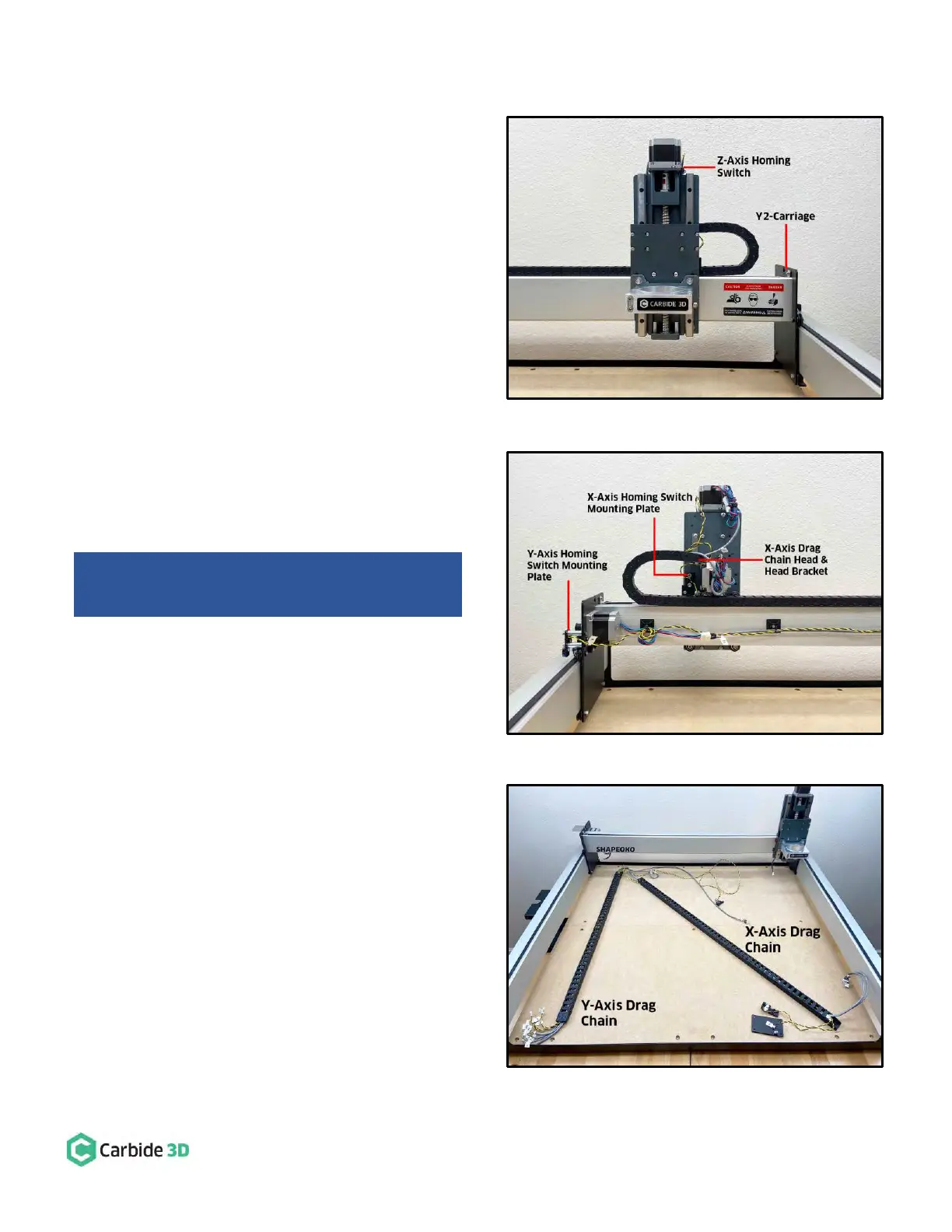
See Fig. 25 (front) and Fig. 26 (back).
1. Remove the Z-Axis homing switch from the top of
the HDZ.
a. Use a 2.5mm hex key to remove the one
(1) M3×12mm SHCS securing the switch to
the Z-motor mount.
2. Remove the X-Axis homing switch mounting plate
from the rear of the HDZ.
a. Use a 4mm hex key to remove the two (2)
M5×35mm SHCS and two (2) 1-inch
spacers. (No need to separate X- or Y-Axis
homing switches from their mounting
plates.)
3. Remove the Y-Axis homing switch mounting plate
from the outside of the Y2-carriage.
a. Use a 4mm hex key to remove the two (2)
M5×35mm SHCS and two (2) 1-inch
spacers.
4. Disconnect the drag chain from the X-Axis head
bracket on the rear of the HDZ.
a. Use a 2mm hex key and needle nose pliers
to remove the two (2) M3×6mm FHS and
two (2) M3 nyloc nuts.
5. Disconnect the drag chain from the Y-Axis head
bracket on the outside of the Y1-carriage.
a. Use a 2mm hex key and needle nose pliers
to remove the two (2) M3×6mm FHS and
two (2) M3 nyloc nuts.
6. Remove the drag chain from the rails and lay it on
the baseframe as shown in Fig. 27.
a. Pry the tail ends of the drag chain from
the VHB tape securing them to the rails.
b. Lay the drag chain on the baseframe for
proximity switch cable installation in the
next section.
c. Remove the VHB tape from the rails.
Shapeoko 3 Machines: Skip 4-6 and move ahead to
“Install the Proximity Switch Mounts” on page 29.