support@carbide3d.com docs.carbide3d.com 10/02/2020 Version 1.0
Connect and Cleanup Cables
Connect the Extension Cables
1. Connect the X- and Z-motor lead cables to their labeled extension cables at the rear of the HDZ.
a. Both the X- and Z-motor extensions exit the head of the X-Axis drag chain behind the HDZ.
b. Connectors are polarized. Be sure to align them properly.
2. Connect the Y1- and Y2-motor lead cables to their extension cables.
a. Both the Y1- and Y2-motor extensions exit the head of the Y-Axis drag chain at the Y1-carriage.
b. The Y2-motor lead cable stretches across the machine, behind the X-rail.
c. Connectors are polarized. Be sure to align them properly.
Connect Cables to the Carbide Motion Board
Required Components:
Shapeoko XXL and XL Instructions
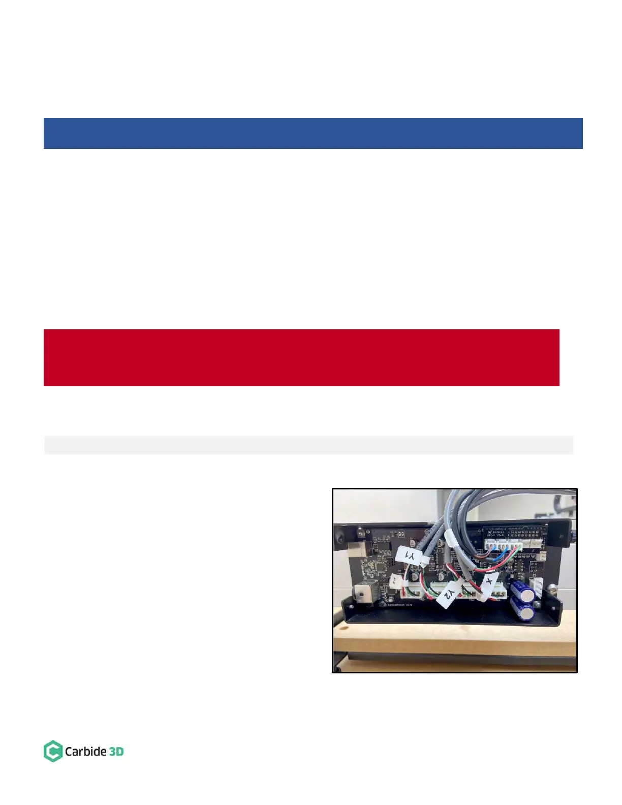
1. Plug the PCB riser board into the Carbide Motion
board. See Fig. 39.
a. Plug the PCB riser board into the 2×8 open
bank of pins in the top-right of the Carbide
Motion board.
2. Plug the proximity switch cables and stepper
motor extension cables into the Carbide Motion
board. See Fig. 39.
a. Plug each of the 3-pin proximity switch
cables, X, Y, and Z, into the PCB riser
board, as labeled.
Shapeoko 3 Machines: Skip ahead to the “Connect Cables to the Carbide Motion Board” section below.
WARNING: The Carbide Motion board can be damaged if the enclosure cover is removed or installed
incorrectly. For correct removal/installation, please watch the Removing the Lid on the Shapeoko Enclosure
video at: https://youtu.be/_wSW5EsFSO0.