EasyManuals Logo

Carbide 3D Shapeoko Proximity Switch Kit User Manual

Default Icon
42 pages
To Next Page IconTo Next Page
To Previous Page IconTo Previous Page
Page #36 background imageLoading...
Page #36 background image
support@carbide3d.com docs.carbide3d.com 10/02/2020 Version 1.0
36
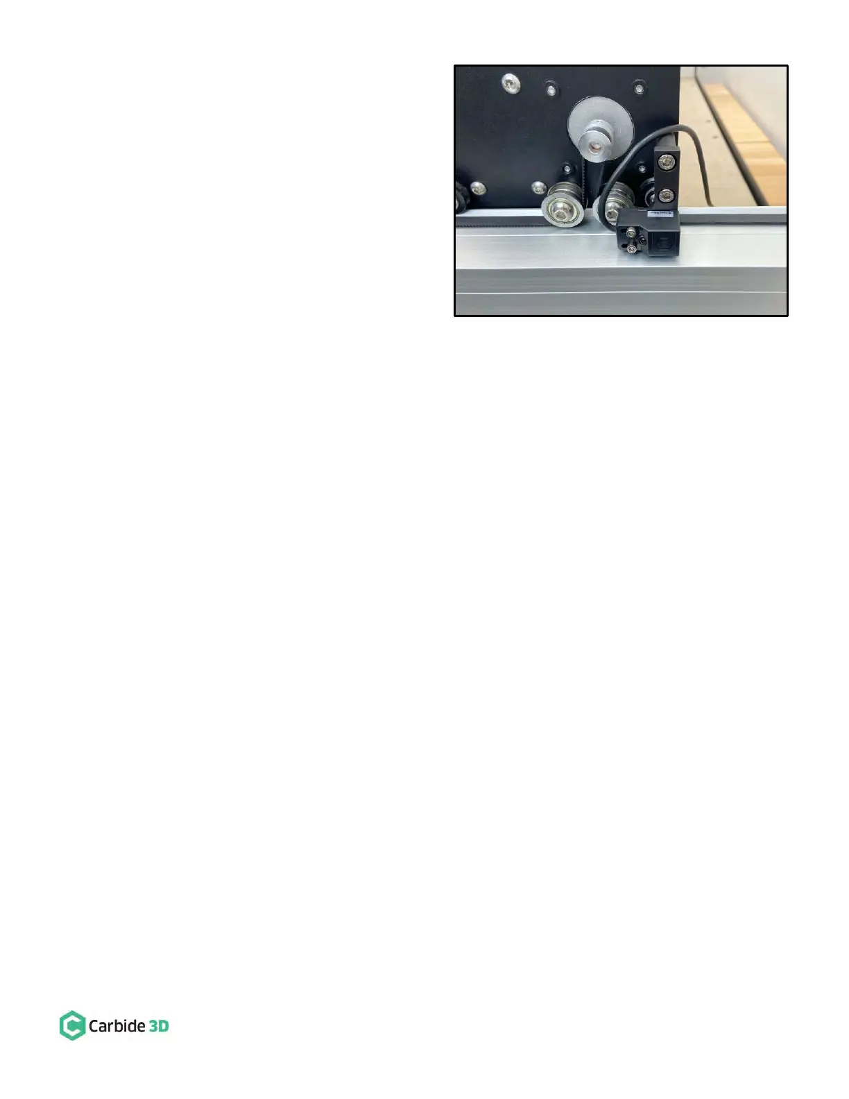
3. Attach Y-Axis proximity switch to the mount on the
outside of the Y2-carriage. See Fig. 38.
a. Locate the Y-Axis proximity switch exiting
the drag chain at the Y-Axis head bracket.
b. Position the proximity switch with the red
LED facing out and the target pointing to
the rear of the machine.
c. Align the switch’s two mounting slots with
the two threaded inserts on the face of
the mount.
d. Use a 2.5mm hex key and two (2)
M3×18mm SHCS to secure.
e. Before fully tightening the screws, slide
the switch as far to the FRONT as it will go.
Figure 38

Questions and Answers:

Question and Answer IconNeed help?

Do you have a question about the Carbide 3D Shapeoko Proximity Switch Kit and is the answer not in the manual?

Carbide 3D Shapeoko Proximity Switch Kit Specifications

General IconGeneral
BrandCarbide 3D
ModelShapeoko Proximity Switch Kit
CategorySwitch
LanguageEnglish