support@carbide3d.com docs.carbide3d.com 10/02/2020 Version 1.0
Attach the X-Axis Proximity Switch to the Mount
Required Components:
X-Axis Proximity Switch (2675mm XXL, 2350mm XL, and 610mm Shapeoko 3)
M3 × 18mm Socket Head Cap Screw
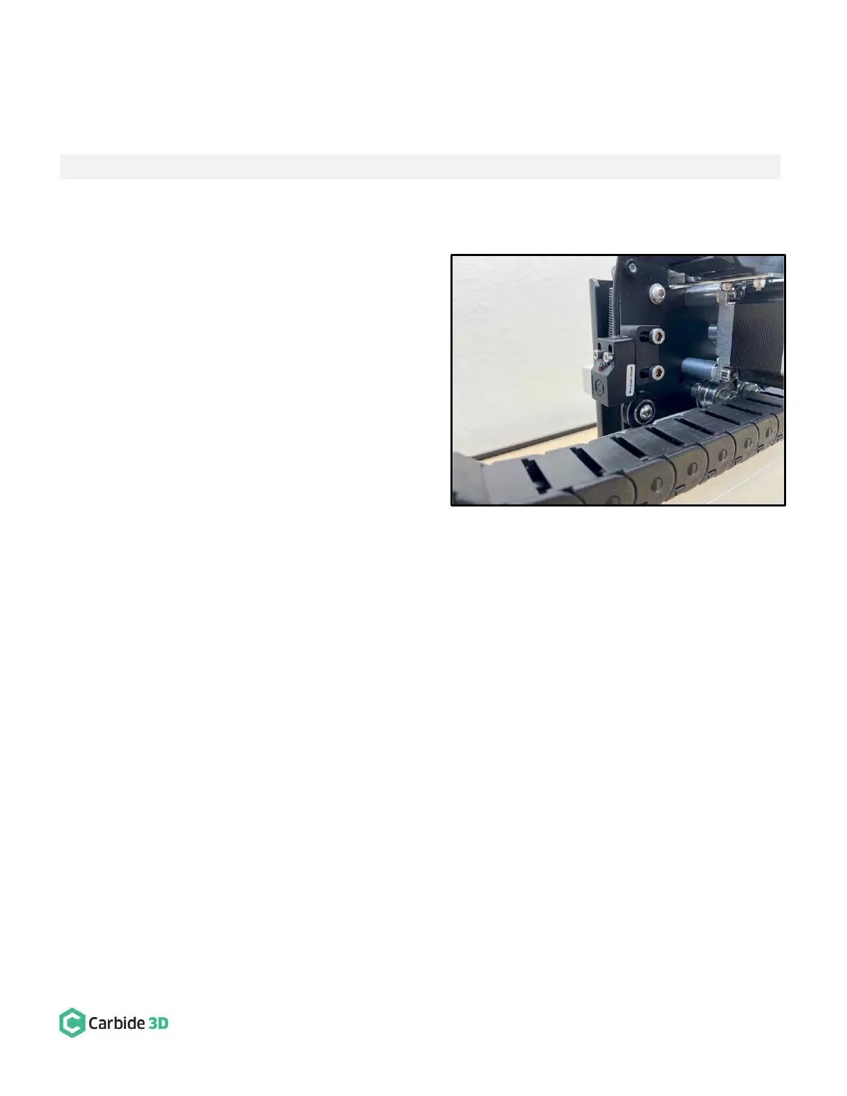
1. Attach the X-Axis proximity switch to the mount
installed on the rear of the X/Z-carriage. See
Fig. 17.
a. Locate the X-Axis proximity switch exiting
the drag chain at the X-Axis head bracket.
b. Position the proximity switch with the red
LED facing the Y2-carriage and the target
pointing down.
c. Align the proximity switch’s mounting
slots with the two threaded inserts on the
face of the mount.
d. Use a 2.5mm hex key and two (2)
M3×18mm SHCS to secure the proximity
switch.
e. Before fully tightening the screws, slide the switch up as far as it will go.