11
ENG
c.pCO sistema +0300057EN rel. 1.2 - 29.05.2017
2. DESIGN
2.1 c.pCO design
On the models where they are included, the front panel contains a display and a
keypad with 6 backlit buttons that, when pressed individually or in combination,
allow the following operations:
• uploading an application program;
• commissioning.
During regular operation and depending on the application program installed,
the terminal can be used:
• to edit the main operating parameters;
• to display the quantities measured, the active functions and any detected
alarm.
C1
NO1
NO2
NO3
C1
C4
NO4
NO5
NO6
C4
C7
NO7
C7
NO8
C8
NC8
NO12
C12
NC12
NO13
C13
NC13
C9
NO9
NO10
NO11
C9
G
G0
U1
U2
U3
GND
+VDC
+Vterm
GND
+5 VREF
U4
GND
U5
GND
VG
VG0
Y1
Y2
Y3
Y4
ID1
ID2
ID3
ID4
ID5
ID6
ID7
ID8
IDC1
U6
U7
U8
GND
ID9
ID10
ID11
ID12
IDC9
ID13H
ID13
IDC13
ID14
ID14H
J1 J24 J2 J3
J4
J5
J7
J8
J20
J21
J14
J10
J13
J12
J22
J16
J17
J18
J15
J6
J19
NO14
C14
NC14
NO15
C15
NC15
C16
NO16
NO17
NO18
C16
ID15H
ID15
IDC15
ID16
ID16H
Y5
Y6
ID17
ID18
IDC17
U9
GND
U10
GND
FieldBus card BMS card
J23 Fus2
J11 pLAN
J25
BMS2
J26
FBus2
43 2 1
A
B
CD
VBAT
G0
G
J30
GND
VREF
S1
S2
S3
S4
DI1
DI2
J29
only model with built-in driver
only model with built-in driver
J27
1
3
2
4
J28
1
3
2
4
A
B
D
H
C
G
F
E
000A5C*
L
M
M
N
U1
U2
U3
GND
U4
U5
U6
GND
U7
U8
U9
U10
GND
J1
J2
G
G0
Vbat
NO1
C1/2
NO2
NO3
C3/4/5
NO4
C3/4/5
NO5
NO6
NC6
C6
+5VREF
GND
+V dc
J9
J10 J11 J12
G/G0: 24 V~ 50...60 Hz / 28...36 V 30 VA/12W
J3 Disp.
+Vterm
J4 FBus
Y1
GND
ID2
ID1
Y2
GND
J8
J7
J5 CAN
LH
A
F
P
B
H
F
N
Verde/Green
Link/Act
Giallo/Yellow
On = 100Mbps
O = 10Mbps
panel mounting
DIN rail mounting
000A5C*
L
c.pCO mini
c.pCO Small...Extralarge
J3 Disp
+Vterm
J4 FBus
NO1
C1/2
NO2
NO3
C3/4/5
NO4
C3/4/5
NO5
NO6
NC6
C6
J10 J11
J12
U1
U2
U3
GND
U4
U5
U6
GND
U7
U8
U9
U10
GND
J1
J2
G
G0
Vbat
J7
+5VREF
GND
+V dc
J9
Y1
GND
ID2
ID1
Y2
GND
J8
J5 CAN
L
H
N
M
P
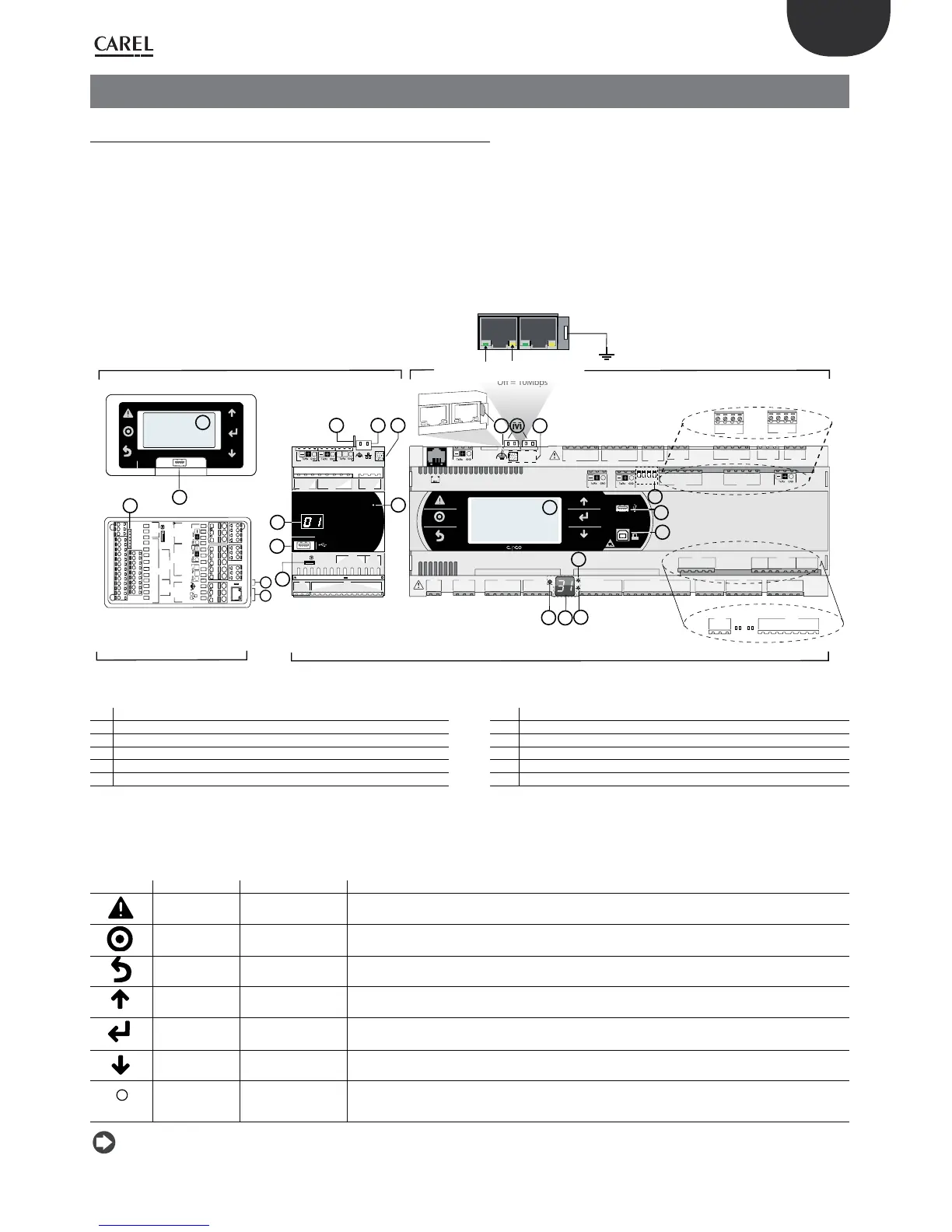
Fig. 2.a
Key:
A Button to set pLAN address G Device USB port (slave)
B Display pLAN address H Main display
C Power LED L MAC address label
D Overload LED M Ethernet port
E Jumpers to select FieldBus/BMS on port J26 N Ethernet port spades
F Host USB port (master) P Single-pole valve connector
Each controller is provided with connectors for the inputs/outputs (see chap. 5) and
the secondary display, which has a button and a LED for setting the pLAN address.
Depending on the model, it can be supplied with a built-in terminal and USB ports.
Keypad
Button Descr. Backlighting Functions
Alarm
White/Red
pressed together with Enter, accesses the screens managed by operating system.
Prg
White/Yellow
-
Esc
White
go back up one level
UP
White
increase the value.
Enter
White
conrm the value
DOWN
White
decrease the value
Select pLAN
address
-
• pressed briey: the pLAN address is displayed brighter
• pressed repeatedly: increase the address
• release: after a few seconds, the brightness is dimmed and the pLAN address is saved
Note: Once the application program is installed, all button functions depend on the program and do not necessarily correspond to the descriptions above.
 Loading...


