8
ENG
c.pCO sistema +0300057EN rel. 1.2 - 29.05.2017
Applications
When provided with a dedicated application program, the controller can be used
to control dierent kinds of equipment:
• chillers and heat pumps;
• roof-top units;
• air-conditioners;
• small/medium-sized air handling units (on request);
• refrigerated showcases (on request and to specications);
• cold rooms (on request and to specications);
• curing rooms;
• compressor racks;
• universal stage controllers.
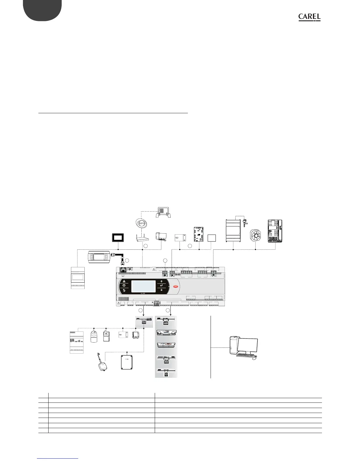
1.1 Functional layout
The gure below shows the functional layout of an air handling unit. Damper
actuators and valve actuators are eld devices that communicate through
Fieldbus 1 (ref. C). Fieldbus 2 (ref. E) is the medium through which the serial probes
communicate the values measured, and through which the humidier control
board and the fans exchange data and receive set points from the controller. The
built-in terminal and the remote terminal, which communicate via pLAN (ref. A),
are used for installing the application program and for commissioning the system.
The PGD touchscreen terminal, intuitive and simple to use, can be used while the
unit is normally working to set switch-on and switch-o times, to enter the main
parameters, to perform other advanced functions of the application program and
to view any alarms triggered. In this case data are exchanged via Ethernet port (ref.
D). In the same network it is possible to connect another c.pCO controller as well
as to communicate with remote cloud service tEra or to BACnet™ supervisor. The
system can be connected to other supervision systems (Konnex®, LON®, etc.) after
installing the relative BMS1 expansion card (ref. B).
584SRsutats
GNX RS485
+ –
P1 P2 P3
BA Cnet
™
MS/TP
FieldBus 1
BMS 1
J1
J24 J2 J3
J4
J5 J7
J8
J20
J21
J14
J10
J13J12
J22
J16 J1
7
J18
J15
J6
J19
FieldBus card
B M S card
J23 FBus2
J11 pLAN
J25 BMS2
J26 FBus2
43 2 1
touch screen
pGD1
FieldBus 2
Ethernet
pLAN
A
D
E
C
B
EVDevolution
c.pCOe
c.pCO mini
tERA cloud
service
Power +
FAN
EVD
Evolution
PC
BELIMO
BELIMO
tDisplay, tService
F
Router
RS485 serial card
FieldBus serial card
Damper
servo-control
Servo-control
valve
Serial probes
th-Tune
Access Point
Speed regulator
pGD terminal
Humidifier
control board
Serial probes
Third part
device
interface
interface
interface
interface
BACnet™ RS485
Ethernet™ /BACnet™
LonWorks ®
Konnex
®
Fig. 1.a
Ref. Serial port/Connectors Connection to:
A pLAN/J10, J11 up to 3 terminals (e.g. pGD1, pLDPRO)
B BMS 1 Serial Card a building automation system, after installing the special BMS card (see par. 1.3)
C FieldBus 1 Serial Card sensors, actuators, etc., on a Fieldbus, after installing the special card (see par. 1.4)
D Ethernet pGD Touch terminals, c.pCO controllers, Router-->tERA
E FieldBus 2 / J26 (e J23 in Large, Extralarge models) sensors, actuators, etc., on a Fieldbus (built-in card)
F BMS 2 / J25 other devices (built-in card)
 Loading...


