61
ENG
c.pCO sistema +0300057EN rel. 1.2 - 29.05.2017
c.pCO SMALL, MEDIUM, BUILT-IN DRIVER, LARGE, EXTRALARGE
Type Relay. Min. contact current: 50 mA.
Maximum no. 8: SMALL; 13: MEDIUM/ BUILT-IN DRIVER; 18: LARGE; 29: EXTRALARGE
Insulation distance
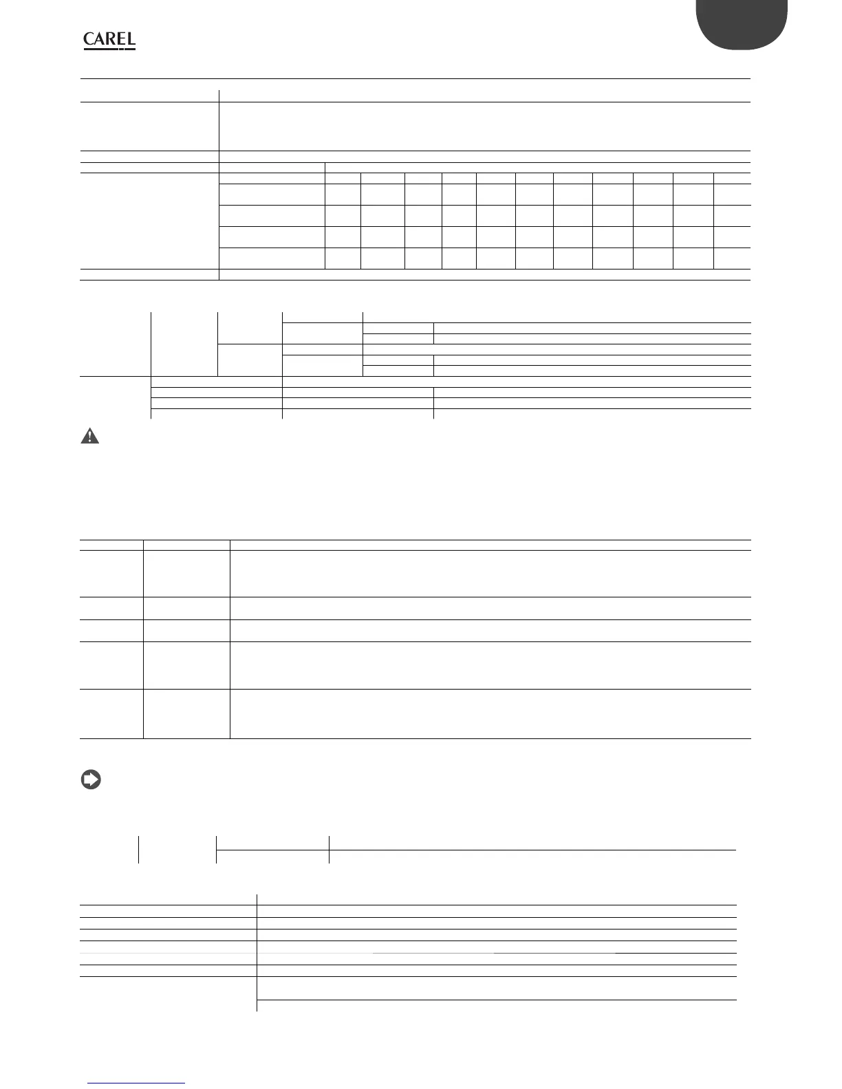
The relay outputs have dierent features depending on the controller model. The outputs can be divided into groups. Relays belon-
ging to the same group (individual cell in the table) have operational insulation and must therefore be powered at the same voltage.
Between groups (between cells in the table) there is reinforced insulation, so the relays can be powered at dierent voltages. There is
also reinforced insulation between each terminal of the digital outputs and the rest of the controller.
Relays with same insulation
Group
Composition of groups
Model 1 2 3 4 5 6 7 8 9 10 11
SMALL 1...3 4...6 7 8 - - - - - - -
Type of relay Type A Type A Type A Type A - - - - - - -
MEDIUM/ BUILT-IN DRIVER 1...3 4...6 7 8 9...11 12 13 - - - -
Type of relay Type A Type A Type A Type A Type A Type A Type A - - - -
LARGE NO 1...3 4...6 7 8 9...11 12 13 14...15 16...18 - -
Type of relay Type A Type A Type A Type A Type A Type A Type A Type A Type A - -
EXTRALARGE 1...3 4...6 7 8 9...11 12 13 14...16 17...20 21...24 25...29
Type of relay Type A Type A Type A Type A Type A Type A Type A Type B Type B Type B Type B
Number of changeover contacts 1: SMALL (relay 8) 3: MEDIUM and EXTRALARGE (relay 8, 12, 13) 5: LARGE NO (relay 8, 12, 13, 14 and 15)
Note: output relays have dierent features depending on the model of
Switchable
power
Type A relay
Rated data SPDT, 2000 VA, 250 Vac, 8A resistive
Approval
UL60730 2 A resistive, 250 Vac, 30,000 cycles Pilot duty C300, 240Vac, 30,000 cycles
EN 60730-1 2(2)A, 250 Vac, 100,000 cycles
Type B relay
Rated data SPST, 1250 VA, 250 Vac, 5A resistive
Approval
UL60730 1 A resistive, 250 Vac, 30,000 cycles Pilot duty C300, 240Vac, 30,000 cycles
1(1), 250 Vac, 100,000 cycles
SSR outputs (on
models where
provided)
Maximum number 1: SMALL (output 7); 2: MEDIUM-EXTRALARGE (outputs 7 and 12); 3 or 4: LARGE (outputs 7, 12, 14 or 7, 12, 14, 15)
Working voltage 24 Vac/Vdc SELV 230Vac
Load current (MAX) 1 A 70mA
Pulse load current (MAX) 1,2 A 150mA
Warning:
• if the load requires a higher current, use an external SSR. To power external loads, use the same power supply as the pCO (connected to terminals G-G0); this must
always be dedicated and not in common with the power supply to other devices (e.g. contactors, coils, etc.);
• to simplify wiring, the groups of digital outputs have two common pole terminals;
• make sure that the current running through the common terminals does not exceed the rated current of each terminal, i.e. 8A.
(*) class 2
Serial ports (for +/- use AWG 20-22 twisted pair shielded cable)
Serial Type/connectors Features
Serial 0 pLAN/J10, J11 • Integrated on main board
• HW driver: asynchronous half duplex RS485 pLAN
• Not optically-isolated
• Connectors: 6-pin telephone jack + 3-pin plug-in, 5.08 pitch
• Maximum length: 500 m
• Max data rate: 38400 bit/s
• Maximum number of connectable devices: 32
Serial ONE BMS 1 Serial Card • Not integrated on main board
• HW driver: not present
• Can be used with all pCO family optional BMS cards
Serial TWO FieldBus 1 Serial
Card
• Not integrated on main board
• HW driver: not present
• Can be used with all pCO family optional FieldBus cards
Serial THREE BMS 2 / J25 • Integrated on main board
• HW driver: asynchronous half duplex RS485 Slave
• Optically-isolated/not optically-isolated serial (*)
• 3-pin plug-in connector, 5.08 pitch
• Maximum length: 1000 m
• Max data rate: 115200 bit/s
• Maximum number of connectable devices: 16
Serial FOUR FieldBus 2 / J26
(and J23 on Large
and Extralarge
version)
• Integrated on main board
• HW driver: asynchronous half duplex RS485 Master/Slave (**)
• J23: not optically-isolated
• J26: optically-isolated/ not optically-isolated
• 3-pin plug-in connector, 5.08 pitch
• J23 and J26 are both managed by the same protocol as serial
4, with the advantage of being electrically independent.
(*): both models are available; (**): port J26 can be congured: see par. 3.2.
Note: in industrial/residential applications with distances greater than 10 m, use shielded cable with earthed shield.
In residential applications (EN 55014), regardless of cable length, in versions without valve driver, the connection cable between controller and terminal and
the serial cable must be shielded and earthed on both sides.
Ethernet RJ45 connector c.pCOmini High End one 10/100 Mbps Ethernet port
cpCO Small...Extralarge two equivalent 10/100 Mbps Ethernet ports (100-BASE TX standard)
c.pCOmini
Single-pole valve output
Number of valves: 1
Maximum output for each valve 8 W
Type of control Single-pole
Valve connector 6-pin, xed sequence
Power supply 13 V ± 5%
Maximum current 0.35 A for each winding
Minimum winding resistance 40 Ω
Max connection cable length
Residential/industrial environments: 2 m without shielded cable, or with shielded cable earthed at both ends
(E2VCABS3U0, E2VCABS6U0)
Residential environment: 2 m without shielded cable
 Loading...


