10
ENG
“EVD ice” +0300038EN - rel. 1.1 - 23.04.2018
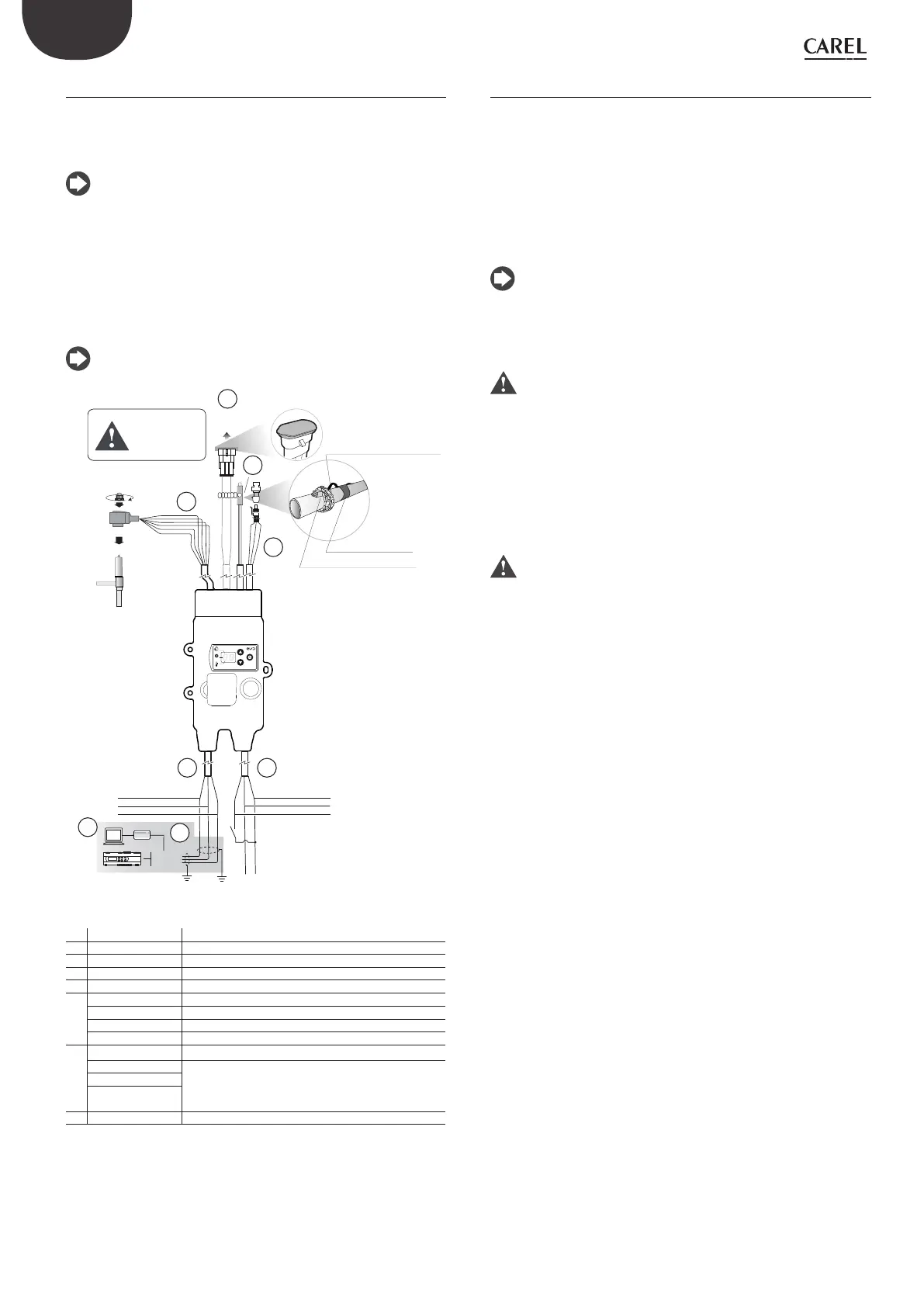
2.4 Wiring description
The driver for superheat control requires the use of an evaporation pressure
probe S1 and suction temperature probe S2, which will be tted downstream
of the evaporator, and a digital input to trigger control. Alternatively, the signal
to trigger control can be sent via a remote serial connection.
Note: input S1 is programmable. See the “Functions” chapter
The following are already wired on EVD ice:
• pressure probe and temperature probe cables;
• electronic expansion valve stator;
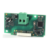
• Ultracap module connection cable (on models where featured);
• power and serial line cables.
The power and serial line connections are identied by the colours of
the wires.
Note: for probe installation see “Guide to EEV system”, (+03022811).
RS485
Modbus®
CVSTDUM0R0
pCO
shield shield
PC
VPM
digital input to start
the regulation
230 Vac
ratiometric
pressure
transducer
Valve stator
0,3 Nm
CAREL E V/ E V
² ³
unipolar valve
NTC
bianco/ white - Tx/Rx+
nero/ black - Tx/Rx-
marrone/ brown - L
blu/ blue - N
nero/ black - DI
S2
ULTRACAP
Module
S1
Non rimuovere
il cappuccio
di protezione A!
Do not remove
the protection cap A!
A
verde/ green - GND
GAS Type
Mode
Super Heat
fascia elastica/ elastic band
fascetta di ssaggio/ fastening band
pasta conduttiva/ conductive cream
B
A
D
1
2
EF
C
Fig. 0.a
Rif Cable Description
A ExV Unipolar electronic valve connection
B Ultracap Ultracap module connection (accessory)
C Probe S2 NTC temperature probe
D probe S1 Ratiometric pressure probe
E Power supply
L: brown Phase 230 V
N: blue Neutral 230 V
DI: black 230 V digital input to enable control
F Serial
Tx/ Rx +: white RS485 connection
Tx/ Rx -: black
GND: green
1 - Computer for conguration
2 - USB– RS485 converter (for computer)
Tab. 0.a
2.5 Wiring
For installation, proceed as shown below, with reference to the wiring
diagrams and the technical specications table:
1. connect the pressure probe that suits the refrigerant. For details on
refrigerant ---> suggested pressure probe, see the chapter on
“Commissioning”;
2. connect the power cable and the digital input cable: for the maximum
length, see the technical specications;
3. power on the driver: the display will light up, and the driver will await the
commissioning parameters. See the chapter on “Commissioning”;
4. program the driver, if necessary: see the “User interface” chapter.
Note: if connecting to a serial network, see the previous diagram for
details on connecting the shield to earth.
Installation environment
Important: avoid installing the drivers in environments with the
following characteristics:
• strong vibrations or knocks;
• exposure to aggressive and polluting atmospheres (e.g.: sulphur
and ammonia fumes, saline mist, smoke) to avoid corrosion and/or
oxidation;
• strong magnetic and/or radio frequency interference (therefore avoid
installing the devices near transmitting antennae);
• exposure of the drivers to direct sunlight and to the elements in
general.
Important: the following warnings must be observed when
connecting the drivers:
• if the driver is used in a way that is not specied in this user manual,
protection cannot be guaranteed;
• incorrect power connections may seriously damage the driver;
• separate as much as possible (at least 3 cm) the probe and digital input
cables from cables to electrical loads, to avoid possible electromagnetic
disturbance. Never run power cables (including the electrical panel
cables) and probe signal cables in the same conduits;
• do not run probe signal cables in the immediate vicinity of power
devices (contactors, circuit breakers, etc.). Reduce the path of probe
cables as much as possible, and avoid spiral paths that enclose power
devices;
• *EVD ice is a controller to be incorporated into the nal equipment; it
must not be wall-mounted;
• * DIN VDE 0100: protective separation must be guaranteed between
the SELV circuits (Safety Extra Low Voltage) and the other circuits. The
requirements of DIN VDE 0100 must be complied with. To prevent
disruption of the protective separation (between the SELV circuits and
the other circuits) ensure additional fastening near the terminations.
This additional fastening must secure the insulation and not the wires.