Nota: nel Modo 3 se si pone C33=1, l’uscita 1 continua a
riferirsi a St1 (e P1), mentre l’uscita 2 si riferisce a St2 (e
P2) che è ora impostabile distintamente.
Il disegno a fianco raffigura la nuova logica.
Da notare che:
1- La stessa funzionalità si sarebbe ottenuta partendo da
Modo 4, modificando “TIPO DI USCITA di OUT2”=C39 da
1 a 0, in modo che l’OUT2 diventasse da “tipo” PWM a
“tipo” ON/OFF.
2- Nel caso si voglia mantenere un unico set point di rego-
lazione si devono mantenere le due uscite dipendenti da St1.
Riprendendo l’esempio precedente basta porre DIPEN-
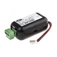
DENZA di OUT2=C38 =1. La figura 33 mostra il nuovo dia-
gramma di regolazione (si noti che i differenziali di lavoro per
OUT1 e per OUT2 fanno riferimento entrambi a P1).
Esempio 15
Si vuole gestire in una cella il comando compressore ed
avere una uscita di allarme.
Soluzione 1: si può utilizzare un regolatore a 2 uscite nel
Modo 5: di fabbrica OUT2 gestisce l’allarme ed OUT1 una
logica di comando Reverse. Sarà sufficiente modificare la
logica di OUT1 per soddisfare la richiesta. St1, P1 e P3
definiscono la regolazione finale.
Modo di partenza: C0=5 salvare la modifica uscendo
dalla programmazione e rientrare in programmazione,
con Passwod 77, ponendo C33=1.
OUT1: uscita ON/OFF che deve passare da logica
Reverse a logica Direct.
INSERZIONE = C36 passa da -100 a +100
DIFFERENZIALE/LOGICA = C37 passa da +100 a -100
(DIPENDENZA e TIPO DI USCITA invariati).
OUT2: già uscita di allarme, restano invariati i parametri.
I parametri P25, P26, P27 e P28 completeranno la pro-
grammazione di allarme temperatura.
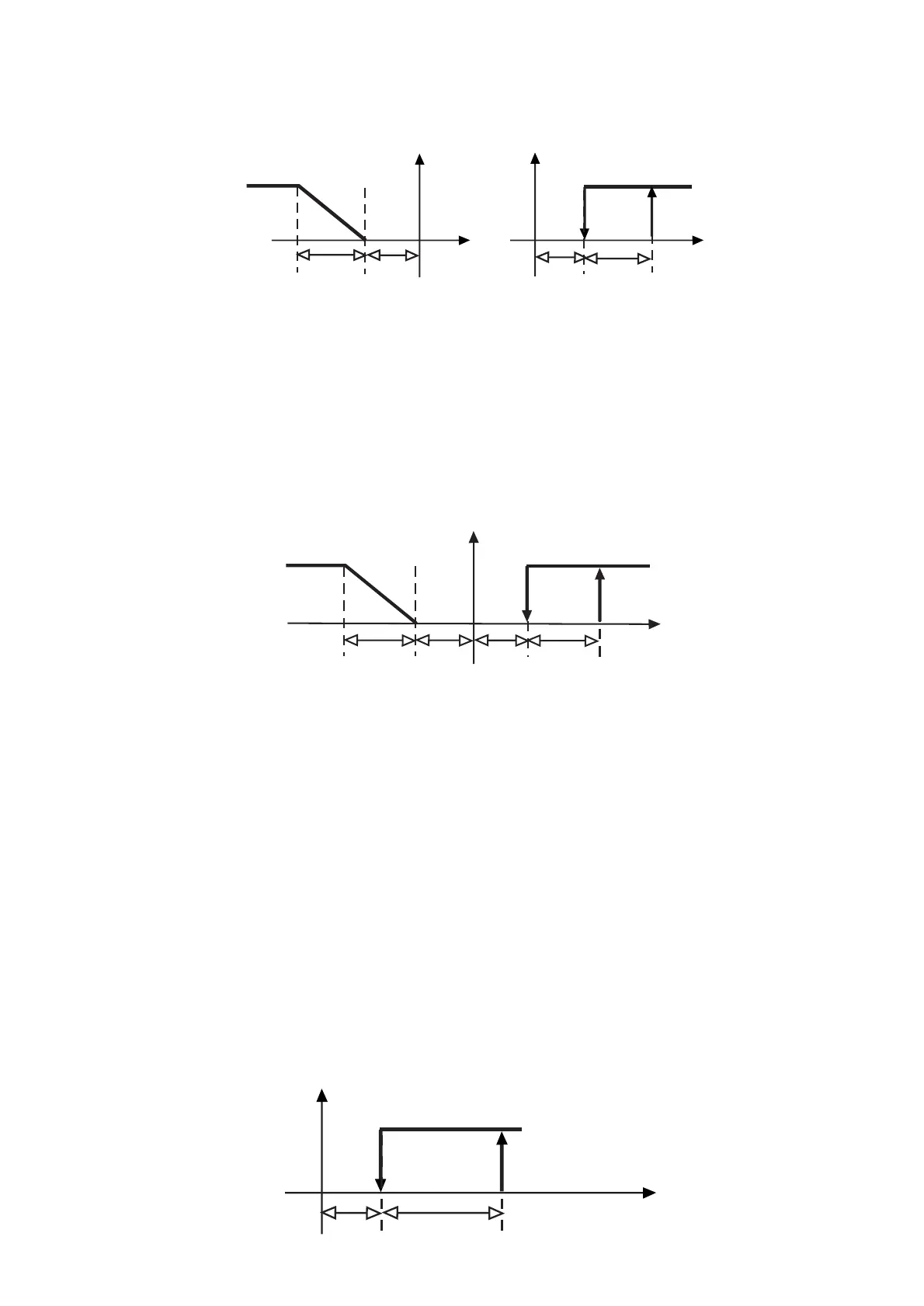
In figura 44 è rappresentata la logica ottenuta.
Note: when working in Mode 3, setting C33=1 implies that the first
output will be directly related to St1 (and P1) whilst output 2 will
be related to St2 (and P2) whose value can be directly selected.
The graph below illustrates the
new operating logic
.
Please note that:
1- the same regulation logic might be achieved starting
from Mode 4 and modifying the TYPE OF OUTPUT relati-
ve to OUT2 as follows: TYPE OF OUTPUT=C39=0, (set-
ting 0 instead of 1 causes the output to work in the
ON/OFF instead of the PWM logic).
2- if you want to maintain only one set-point, the two out-
puts must be related to St1. Set Dependence of
Out2=C38=1. Fig. 33 shows the new control graph (diffe-
rentials for OUT1 and OUT2 refer to P1).
Example no. 15:
Control of a single-compressor cold storage room with
one alarm output.
Solution 1: use a two-output controller and set Mode 5 so
that OUT2 will manage the alarm and OUT1 the REVER-
SE mode. To meet the above application requirement, all
you have to do is modify the control logic of OUT1.
Starting Mode: C0=5; confirm the variation by exiting the
programming field, then enter again (password 77) and
set C33=1.
OUT1: ON/OFF output, from Reverse to Direct mode
ENERGIZATION = C36 changes from -100 to +100
DIFFERENTIAL/LOGIC = C37 changes from +100 to -100
(Dependence and Differential/Logic unchanged)
OUT2: used as alarm output (parameters remain unchan-
ged). P25, P26, P27 and P28 allow you to complete the
programming step by setting the temperature alarms.
The graph below (fig. 44) shows the new control logic:
55
 Loading...