Soluzione 2: questa applicazione può essere sviluppata
dal Modo di partenza, ovvero da C0=2, disinteressando
così il Differenziale di zona NEUTRA P3. Di seguito elen-
chiamo la lista dei parametri speciali che si vanno a modi-
ficare, partendo senza alterare C0=2, entrando diretta-
mente con Password 77 su C33=1: C36=+100, C37=-100
e C38=3 (inalterati gli altri). P25, P26, P27 e P28 comple-
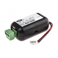
tano la programmazione delle uscite di allarme. Il disegno
della figura 45 mostra la logica che si ottiene con questa
soluzione:
Esempio 16
Un’unità di condizionamento ha una resistenza per riscal-
dare e 3 compressori per raffreddare. Uno dei 3 compres-
sori ha potenza doppia rispetto agli altri due. Inoltre si
richiede di gestire la resistenza con logica PWM.
Soluzione: si utilizzerà un controllo a 4 uscite, OUT1 per
comandare la resistenza con funzionamento PWM, OUT2
per comandare il compressore maggiore e per il quale si
vuole un’isteresi doppia rispetto agli altri due. OUT3 e
OUT4 pilotano gli altri due compressori.
Modo di partenza: si può partire dal Modo standard C0=2
con P.W.77 modificare C33=1. Vediamo come strutturare i
parametri affinché resistenza e compressori siano dipen-
denti da due set point e differenziali distinti.
OUT1:
uscita ON/OFF per comando della resistenza in PWM
DIPENDENZA=C34=1 resta invariato,
TIPO DI USCITA=C35=1, INSERZIONE=C36=-100
DIFFERENZIALE/LOGICA=C37=+100
OUT2:
uscita ON/OFF per comando del compressore maggiore
DIPENDENZA=C38 passa da 1 a 2 (l’uscita si riferisce ora a St2)
TIPO DI USCITA=C39=0 resta invariata,
INSERZIONE=C40=+50, DIFFERENZIALE/LOGICA=C41=-50
OUT3:
uscita ON/OFF per comando del secondo compressore
DIPENDENZA=C42=2, TIPO DI USCITA=C43=0, INSER-
ZIONE=C44=+75, DIFFERENZIALE/LOGICA=C45=-25
OUT4:
uscita ON/OFF per comando del terzo compressore
DIPENDENZA=C46=2, TIPO DI USCITA=C47=0, INSER-
ZIONE=C48=+100, DIFFERENZIALE/LOGICA=C49=-25
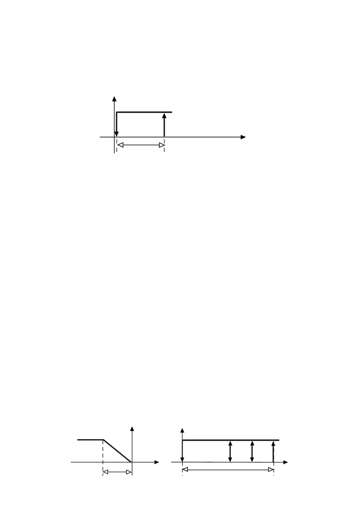
Il grafico rappresenta la logica di funzionamento selezio-
nata. L’azione del riscaldamento è in funzione di St1, P1 e
C12. La gestione dei compressori dipende da St2 e P2.
Solution 2
:
set C0=2 so that the Differential of NEUTRAL
zone P3 will not be considered. Special parameters to be
modified when C0=2 (use password 77). C33=1:
C36=+100, C37=-100, C38=3 (the other parameters
remain unchanged). P25, P26, P27 and P28 allow you to
complete the programming step by setting the temperatu-
re alarms. The graph below (fig. 45) shows this control
logic:
Example no. 16
Control of an air-conditioning unit equipped with one hea-
ter and 3 compressors. The capacity of one of the com-
pressors is twice the capacity of the other two. PWM logic
is required to control the heater.
Solution: use a 4-output controller. OUT1 will control the
heater in PWM, OUT2 the main compressor whose hyste-
resis has to be twice the size of the other two. OUT3 and
OUT4 will control the other two compressors.
Starting Mode: standard C0=2 (password 77).Then set
C33=1. Set the other parameters so that heater and com-
pressors will depend on two different set-points and differentials.
OUT1:
ON/OFF output to control the heater with PWM logic
DEPENDENCE=C34=1 unchanged
TYPE OF OUTPUT C35=1, ENERGIZATION C36=-100
DIFFERENTIAL/LOGIC C37=+100
OUT2:
ON/OFF output to actuate the main compressor
DEPENDENCE=C38 changes from 1 to 2
(as the output must refer to St2)
TYPE OF OUTPUT=C39=0 unchanged
ENERGIZATION=C40=+50
DIFFERENTIAL/LOGIC=C41=-50
OUT3:
ON/OFF output to actuate the second compressor
DEPENDENCE=C42=2 TYPE OF OUTPUT=C43=0
ENERGIZATION=C44=+75 DIFFERENTIAL/LOGIC=C45=-25
OUT4:
ON/OFF output to actuate the third compressor
DEPENDENCE=C46=2 TYPE OF OUTPUT=C47=0
ENERGIZATION=C48=+100 DIFFERENTIAL/LOGIC=C49=-25
The graph shows the control logic described above.
Heating depends on St1, P1 and C12. Cooling depends
on St2 and P2.
56
 Loading...