+050004104 rel. 2.2 del 26.09.07
11
ENGLISH
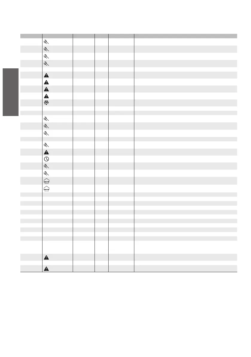
5. TABLE OF ALARMS AND SIGNALS: display, buzzer and relay
The following table describes the alarms and the signals on the controller, with the corresponding description, status of the buzzer, the alarm relay and the
reset mode.
Code Icon on the display Alarm relay Buzzer Reset Description
‘rE’
flashing
active active automatic virtual control probe fault
‘E0’
flashing
off off automatic room probe S1 fault
‘E1’
flashing
off off automatic defrost probe S2 fault
‘E2’-3-4
flashing
off off automatic probe S3-4-5 fault
‘___’ no off off automatic probe not enabled
‘LO’
flashing
active active automatic low temperature alarm
‘HI’
flashing
active active automatic high temperature alarm
‘AFr’
flashing
active active manual antifreeze alarm
‘IA’
flashing
active active automatic immediate alarm from external contact
‘dA’
flashing
active active automatic delayed alarm from external contact
‘dEF’ on off off automatic defrost running
‘Ed1’-2 no off off autom./manual defrost on evaporator 1-2 ended by timeout
‘Pd’
flashing
active active autom./manual maximum pump-down time alarm
‘LP’
flashing
active active autom./manual low pressure alarm
‘AtS’
flashing
active active autom./manual autostart in pump-down
‘cht’ no off off autom/manual high condenser temperature pre-alarm
‘CHT’
flashing
active active manual high condenser temp.
‘dor’
flashing
active active automatic door open for too long alarm
‘Etc’
flashing
off off autom./manual real time clock fault
‘EE’
flashing
off off automatic unit parameter EEPROM error
‘EF’
flashing
off off automatic operating parameter EEPROM error
‘HA’
flashing
off off manual HACCP alarm type ‘HA’
‘HF’
flashing
off off manual HACCP alarm type ‘HF’
‘rCt’ Signal Instrument enabled for programming from remote control
‘Add’ Signal Automatic address assignment procedure in progress
‘Prt’ Signal Report being printed
‘LrH’ Signal Activation of the low relative humidity procedure
‘HrH’ Signal Activation of the high rH procedure
‘ccb’ Signal Request start continuous cycle
‘ccE’ Signal Request end continuous cycle
‘dFb’ Signal Request start defrost
‘dFE’ Signal Request end defrost
‘On’ Signal Switch ON
‘OFF’ Signal Switch OFF
‘rES’ Signal Reset alarms with man. reset;
Reset HACCP alarms;
Reset temp. monitoring
‘n1’ to ‘n6’
flashing
active active automatic Indicates alarm on unit 1 to 6 present in the network
‘dnL’ Signal Download in progress
‘d1’ to ‘d6’
flashing
off off Download with errors on unit 1 to 6
Tab. 5.a
Notes: The buzzer is activated if enabled by parameter ‘H4’.
The alarm relay is activated if one of the auxiliary outputs, AUX (‘H1’) or AUX2 (‘H5’), has been assigned the alarm relay function (normally energised or
de-energised).
 Loading...


