EasyManuals Logo

Carel mastercella Technical Leaflet

Carel mastercella
To Next Page IconTo Next Page
To Previous Page IconTo Previous Page
Page #23 background imageLoading...
Page #23 background image
+050004104 rel. 2.2 del 26.09.07
15
7. RECOMMENDED CURRENT ACCORDING TO THE CROSS-SECTION OF THE
WIRES
AWG Cross-section (mm
2
) Current
24 0.21 0.8
23 0.26 1
22 0.33 1.3
21 0.41
0.5
1.6
2
20 0.52 2.1
19 0.65 2.6
18 0.82 3.3
17 1 4
16 1.31
1.5
5.3
6
15 1.65 6.8
14 2.1
2.5
9
12
13 2.63 12.8
12 3.31 16.1
Tab. 6.a
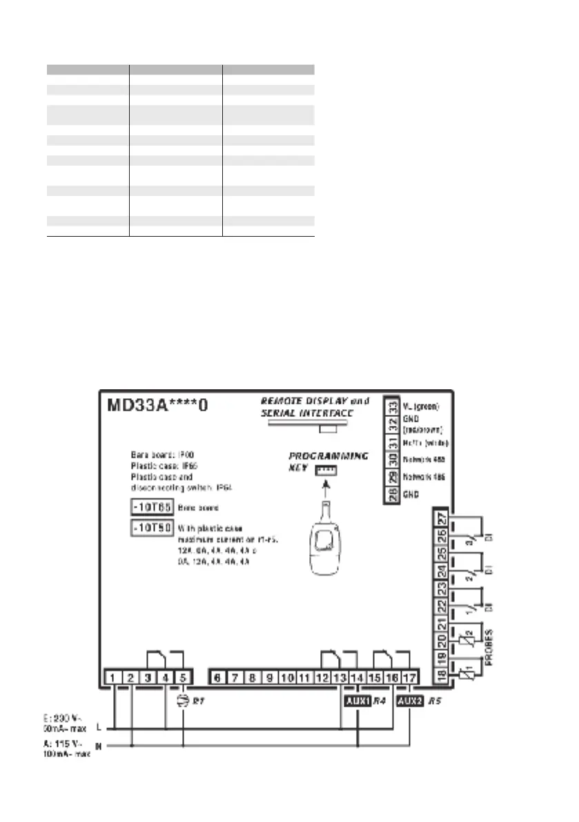
8. CONFIGURATIA ELECTRICA/ELECTRICAL CONFIGURATIONS/
BRANCHEMENTS ÉLECTRIQUES/ELEKTRISCHE ANSCHLÜSSE/CONEXIONES
ELÉCTRICAS/LIGAÇÕES ELECTRICAS
MD33(A,D) (0,1,2,3,4,5) (A,B,E,F) (N,R,C,B) (0,1,2,3,4,5,6,7) 0
Fig. 7.a

Other manuals for Carel mastercella

Questions and Answers:

Question and Answer IconNeed help?

Do you have a question about the Carel mastercella and is the answer not in the manual?

Carel mastercella Specifications

General IconGeneral
SeriesMastercella
Front ProtectionIP65
Protection RatingIP65 (front)
Control TypePID, ON/OFF
DisplayLCD
InputsNTC, PT1000
OutputsRelay, SSR
Storage Temperature-30°C to +70°C
Analogue Outputs4-20 mA, 0-10 V
Serial CommunicationRS485, Modbus RTU
Relative Humidity<90% RH non-condensing

Related product manuals