+050004104 rel. 2.2 del 26.09.07
3
ENGLISH
1. INTRODUCTION
MasterCella is the new electronic controller for static or ventilated refrigerating units, able to manage all the actuators normally featured, such as:
compressors, fans, defrost, alarms and lights. The MasterCella case is IP65 and the electrical wiring is especially simple, due to the fact that the front panel
can be removed. The MasterCella case allows installation either on the panel or on the wall.
2. OPTION CODES
CODE DESCRIPTION
IRTRRES000 small infrared remote control
IROPZSEM10 RS485 serial board with automatic recognition of the polarity +/-
IROPZSEM30 RS485 serial board with automatic recognition of the polarity +/- and connection of repeater display
PST00VR100 remote repeater display
IR00RG0000 remote repeater display ir33 range green display
IR00RR0000 remote repeater display ir33 range red display
PSTCON0300 connection cables to the repeater display, one end with screw, 3 metres long
PSTCON1000 connection cables to the repeater display, one end with screw, 10 metres long
PSOPZKEY00 parameter programming key with 12V batteries included
PSOPZKEYA0 parameter programming key with external 230 Vac power supply
IROPZKEY00 parameter programming key with extended memory and 12V batteries included
IROPZKEYA0 parameter programming key with extended memory and external 230 Vac power supply
VPMSTDKY*0(1,2) programming key kit
MDOPZCA000 optional board with 3 repeat connectors
MDOPZCB000 optional board with 5 repeat connectors
0402512CEL Disconnecting switch 32 A
0402515CEL Shaft H= 85 mm
0402517CEL Yellow/red disconnecting switch
Tab.2.a
3. DISPLAY
MasterCella is fitted with a three digit LED display for the temperature, and icons for displaying the operating status. It can also be connected, using a special
interface, to a further display, used, for example, to show the reading of the third probe.
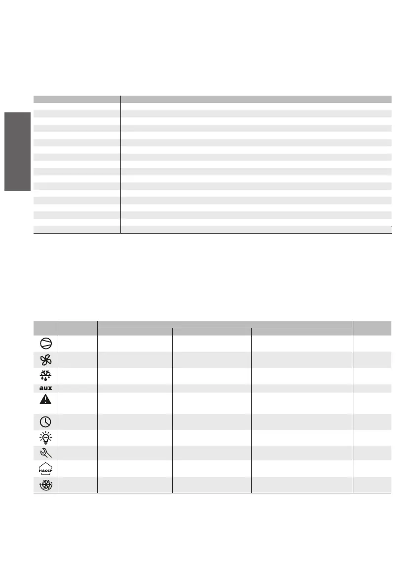
3.1 Signals on the display
Icon Function Normal Operation Startup
ON OFF flashing
COMPRESS. compressor on compressor off compressor call
FAN fan on fan off fan call
DEFROST defrost in progress no defrost call defrost call
AUX AUX auxiliary output active AUX auxiliary output not active anti-sweat heater function active
ALARM delayed external alarm (before
the time A7’ has elapsed)
no alarm present alarms in norm. operation (e.g. high/low
temperature) or alarm from external digital
input, immediate or delayed
CLOCK if at least one timed defrost has
been set
no timed defrost set clock alarm ON if Real-Time
Clock present
LIGHT LIGHT auxiliary output active LIGHT auxiliary output not active anti-sweat heater function active
SERVICE no malfunction malfunction (e.g. EEPROM error or probes
faulty)
HACCP HACCP function enabled HACCP function not enabled HACCP alarm saved (HA and/or HF)
CYCLE CONTINUOUS CYCLE
function activated
CONTINUOUS CYCLE function
not activated
CONTINUOUS CYCLE function call
Tab. 3.a
The flashing status indicates that the function has been called but cannot be run until the delay timers expire.