+050004104 rel. 2.2 del 26.09.07
13
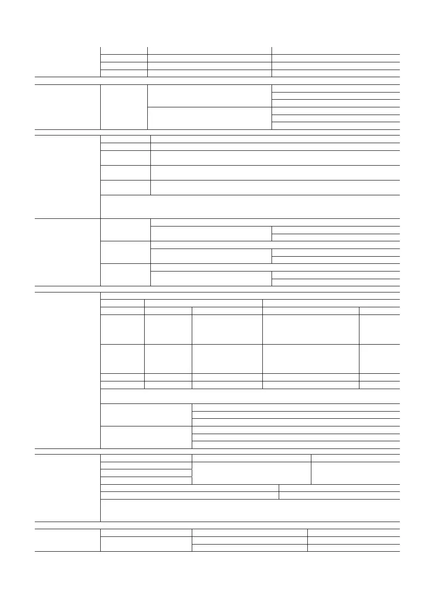
6. ELETTRICAL SPECIFICATIONS
Power supply
Model Voltage Power
E 230 V~, 50-60Hz 11,3VA, 50mA~ max
A 115 V~, 50-60Hz 11,3VA, 100mA~ max
H not avalaible 115-230 V~, 50-60Hz 12VA, 110mA~ max
Insulation guaranted by the
power supply
E, A, (H not
avalaible)
insulation in reference to very low voltage parts
reinforced
6mm clearance, 8 creepage
3750V insulation
insulation from relay outputs
basic
3mm clearance, 4 creepage
1250V insulation
Inputs
S1 NTC or PTC (depending on the model)
S2 NTC or PTC (depending on the model)
DI1
S3
free contact, contact resistance < 10ohm, closing current 6mA
NTC or PTC (depending on the model)
DI2
S4
free contact, contact resistance < 10ohm, closing current 6mA
NTC or PTC (depending on the model)
DI3
S5
free contact, contact resistance < 10ohm, closing current 6mA
NTC or PTC (depending on the model)
Maximum ditance of probes and digital inputs less than 10 m.
Note: during installation keep the power and loads connection separate from probe cables, digital inputs, repeater display and
supervisory system.
Probe type
NTC std. CAREL
10kΩ a 25°C, range from –50°C to +90°C
measurement error:
1°C in the range from –50° C to +50°C
3°C in the range from +50° C to +90°C
NTC high tempe-
rature
50kΩ a 25°C, range from –40°C a +150°C
measurement error:
1,5°C in the range from –20° C to +115°C
4°C in the range from -20° C to +115°C
PTC std. Carel
(specific model)
985 Ω a 25°C, range da -50°C a 150°C
measurement error:
2°C in the range from –50° C to +50°C
4°C in the range from +50° C to +150°C
Relè outputs
depending on the model
EN60730-1 UL 873
250V~ operating cycle 250V~ operating cycle
8 A (**) 8 (4) A su N.O.
6 (4) A su N.C.
2 (2) A su N.O.
e N.C.
100000 8A res 2FLA 12LRA C300 30000
16 A (**) 10 (4) A fino a 60°C
su N.O.
12 (2) A su N.O.
e N.C.
100000
12A res 5FLA 30LRA C300 30000
2HP 10 (10) A 100000 12A res 12FLA 72LRA 30000
30 A (**) 12 (10) A 100000 12A res 2HP 12FLA 30000
(**) Relay not suitable for fluorescent loads (neon lights, ...) that use starters (ballasts) with phase-shift capacitors. Fluorescent lamps with
electronic control devices or without phase-shift capacitors can be used, within the operating limits specified for each type of relay.
insulation from very low voltage parts
rinforced
6mm clearance, 8 creepage
3750V insulation
insulation between relay outputs
indipendent
principale
3mm clearance, 4 creepage
1250V insulation
Connection
Type of connection Sections Cross sections max current
screw
for cable from 0,5 to 2,5 mm
2
12A
removible for screw blocks
faston
Section conduttors for probes and digital inputs from 0,5 to 2,5 mm
2
(da 20 a 13 AWG)
Section conduttors for power supply and loads from 1,5 to 2,5 mm
2
(da 15 a 13 AWG)
the installer has to provide the correct dimensioning of the power supply and cable connection between the instruments and the loads.
Depending on the model, the maximum current in the common terminals 1, 3 and 5 is 12 A. When using the controller at maximum
operating temperature and full load, use cables featuring a maximum operating temperature of 105 °C at least.
Case
plastic dimensions 200x240x93 mm
board and frontal
board dimensions 178x86x40 mm
frontal dimensions 100x90x12 mm
 Loading...


