54
ENG
mpxone +0300086EN rel. 2.2 - 13.11.2023
Functions
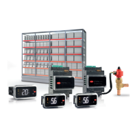
Duty cycle with ON/OFF compressor
Check end
Regulation
Regulation Calling Defrost Defrost Running
Defrost
Status
(dFS)
Evaporator
Fan
Status
(FOI)
Compressor
Request
(vSr)
Hot gas
valve
position
Liquid
valve
status
CLOSED
OPEN
Dripping
dd Fd
Post Dripping
1
1
1
1
2
3
4
5
F3
Fpd
pump down
dHG/2
dHG/2
dGH dGH
Fig. 5.r
Ref. Par Description
pos. dSb valve positioning during defrost
t pos. Pdd time position held after defrost
evap F3 evap fan status during defrost
evap Fpd evap fan status during post-dripping
drip dd dripping
post drip Fd post-dripping
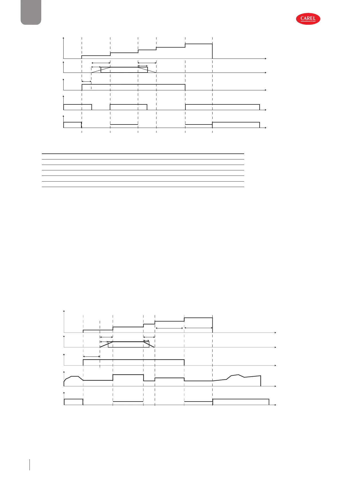
VCC compressor
For hot gas defrost with a VCC compressor, if valves with a long actuation time are used, it may be necessary to equalise the
pressure in the circuit before circulating the hot gas in the evaporator.
To do this:
– open the liquid valve located upstream of the evaporator
– start the compressor with a delay.
The parameter that defi nes the hot gas valve activation time is “dHG”.
dHG must be greater than or equal to the time declared by the manufacturer for complete movement of the valve.
When a defrost is called, the hot gas valve starts opening before the active defrost phase begins.
Similarly, on ending the defrost phase, the valve starts to close before the actual end of the procedure.
– Defrost start: compressor off or on, according to the control status and settings, liquid valve open, the hot gas valve is sent
the command to switch over;
– Active defrost phase: the hot gas valve valve continues changing status until reaching the fi nal position, the liquid valve is
closed and the compressor is started (frequency=cdF);
– End defrost: the hot gas valve begins moving, the compressor is kept on at minimum speed (frequency=cnf ), the liquid
valve remains closed; at the end of the hot gas valve movement, the next phase starts (dripping, post -dripping, control).
Check end RegulationRegulation Calling Defrost Defrost Running
Defrost
Status
(dFS)
Evaporator
Fan
Status
(FOI)
Compressor
Request
(vSr)
Hot gas
valve
position
Liquid
valve
status
CLOSED
OPEN
Dripping
dd
Fd
Post Dripping
1
1
1
1
2
3
4
5
F3
Fpd
pump down
dHG/2
dHG/2
dGH
cnf cdf cnf ddf
dGH
Fig. 5.s
 Loading...