pCO Sistema
Code: +030220336 - rel. 1.5 - 22/12/10
17
• pCO
pCOpCO
pCO
1
11
1
digital outputs
digital outputsdigital outputs
digital outputs
Insulation distance
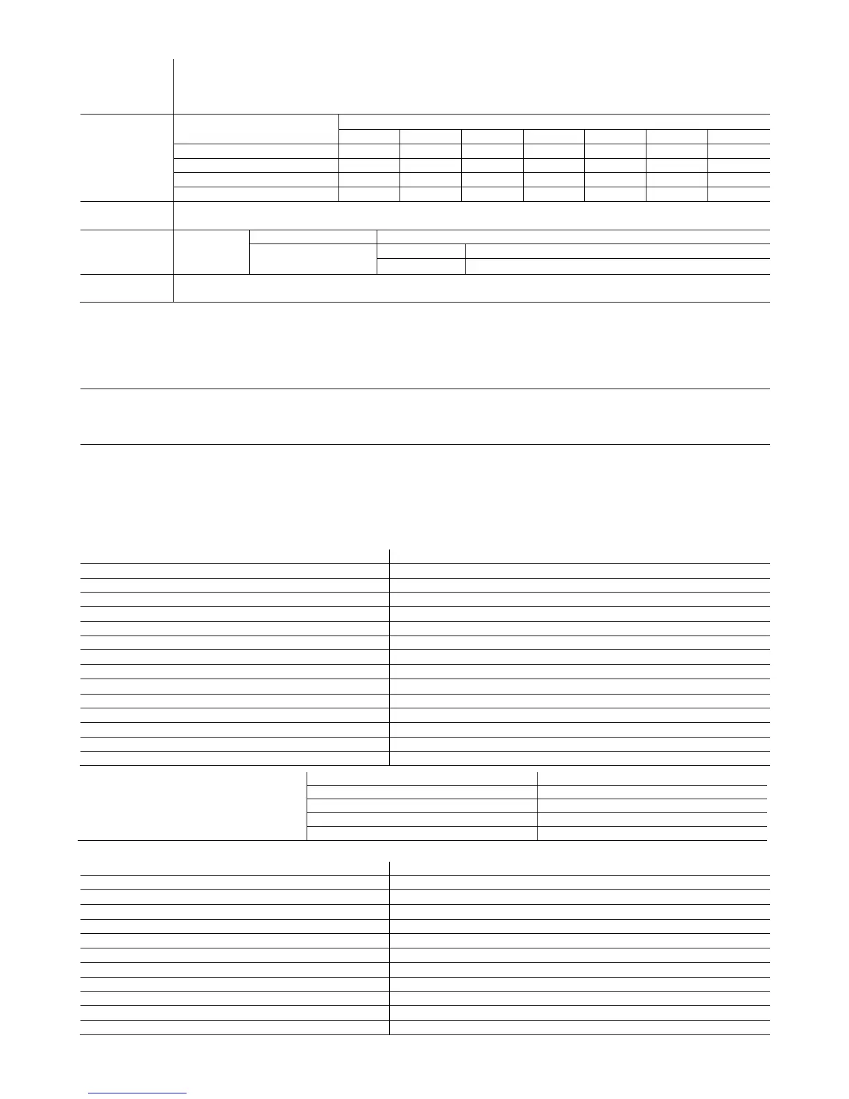
The relay outputs have different features depending on the model of pCO
The outputs can be divided into groups. There is double insulation between the groups (cells in the table) and consequently these may have
different voltages. There is also double insulation between each terminal of the digital outputs and the rest of the controller. The relays belonging to
the same group (individual cells in the table) have basic insulation and therefore must have the same power supply (24 Vac or 230 Vac).
Makeup of the
groups
Version Reference of the relays with the same insulation
Group 1 Group 2 Group 3 Group 4 Group 5 Group 6 Group 7
SMALL
SMALLSMALL
SMALL
1 to 3 4 to 6 7 8
Type of relay Type A Type A Type A Type A
MEDIUM
MEDIUMMEDIUM
MEDIUM
1 to 3 4 to 6 7 8 9 to 11 12 13
Type of relay Type A Type A Type A Type A Type A Type A Type A
Number of
changeover contacts
1: SMALL (output 8); 3: MEDIUM (outputs 8, 12 and 13);
Switchable power Relay type A
Relay ratings SPDT, 2000 VA, 250 Vac, 8 A resistive
pCO
1
approval
UL873 2.5 A resistive, 2 A FLA, 12 A LRA, 250 Vac, C300 pilot duty (30,000 cycles)
EN 60730-1 2 A resistive, 2 A inductive, cos
=0.6, 2(2)A (100,000 cycles)
Maximum number
of SSR outputs
2: SMALL (output 7 and 8); 4: MEDIUM (outputs 7, 8, 12 and 13);
Electrical specifications: working voltage 24 Vac/Vdc, maximum switchable output 10 Watts
Warnings:
• The groups that the digital outputs are divided into have two common pole terminals to simplify wiring.
• Make sure that the current running through the common terminals does not exceed the rated current of an individual terminal, that is, 8 A
• pCO
pCOpCO
pCO
1
11
1
mechanical specifications
mechanical specificationsmechanical specifications
mechanical specifications
Mechanical dimensions
SMALL
SMALLSMALL
SMALL
13 DIN modules 110 x 227.5 x 60mm
MEDIUM
MEDIUMMEDIUM
MEDIUM
18 DIN modules 110 x 315 x 60mm
Plastic container
Assembly Fitted on DIN rail as per DIN 43880 and IEC EN 50022
Material technopolymer
Flame retardancy V0 (UL94) and 960°C (IEC 695)
Ball pressure test 125°C
Resistance to creeping current
250 V
Colour Grey RAL7035
• pCO
pCOpCO
pCO
1
11
1
other features
other featuresother features
other features
Operating conditions -10T60°C, 90% RH non-condensing
Storage conditions -20T70°C, 90% RH non-condensing
Index of protection IP20, IP40 on the front panel only
Environmental pollution 2
Class according to protection against electric shock to be integrated into Class 1 and/or 2 appliances
PTI of the insulating materials 250 V
Period of stress across the insulating parts long
Type of action 1C
Type of disconnection or microswitching microswitching, for all relay outputs
Category of resistance to heat and fire Category D
Immunity against voltage surges Category 1
Ageing characteristics (operating hours) 80,000
No. of automatic operating cycles 100,000 (EN 60730-1); 30,000 (UL 873)
Software class and structure Class A
Category of immunity to voltage surges (IEC EN 61000-4-5) Category 3
Error in the temperature range
typically 6 months (maximum 8 months)
typically 5 hours (<8 hours maximum)
• pCO
pCOpCO
pCO
1
11
1
electrical specifications
electrical specificationselectrical specifications
electrical specifications
Power supply 24 Vac +10/-15% 50/60 Hz and 22 to 38Vdc +10/-20%
Maximum current with terminal connected P=13 W
Type of insulation of the power supply from the rest of the controller -
Terminal block with male/female plug-in connectors (250 Vac max, 8 A max)
Cable cross-section min 0.5 mm
CPU H8S2320, 16 bit, 14 MHz
Program memory (FLASH MEMORY) 2 Mbyte, 16 bit
Data memory (RAM) 512 Kbyte, 8 bit
T memory, buffer (FLASH MEMORY) 4 Kbyte, 16 bit
P memory, parameters (EEPROM) optional (32 Kbyte not available to the pLAN network)
Working cycle duration (application of average complexity) 0.5 s
Clock with battery optional
 Loading...


