pCO Sistema
Code: +030220336 - rel. 1.5 - 22/12/10
22
2.7 pCO
C
controller
1
10
13
4
5
15
14
13
2
11
12
J17
J11
J20
J21
J22
J24
J1
J2
J3
J4
J5
J6
B8
+24Vdc
B7
B6
AVSS
B5
B4
AVSS
B3
B2
AVSS
B1
IDCM2
ID10
ID9
ID8
ID7
ID6
IDCM1
ID5
ID4
ID3
ID2
ID1
C1
NO1
-------
C2
NO2
C3
NO3
-------
C4
NO4
-------
C5
NO5
-------
C12
NO12
NO8
C8
-------
NO7
C7
-------
NO6
C6
-------
NO13
C13
NO11
C11
NC11
--------
NO10
C10
NC10
--------
NO9
C9
NC9
ID230
ID24
ID11R
--------
ID12R
ID24
ID230
VG0
VG1
Y1
Y0
G
G0
J19
pCO
c
I/O board
GND
RX/TX-
RX/TX+
3
7
6
9
8
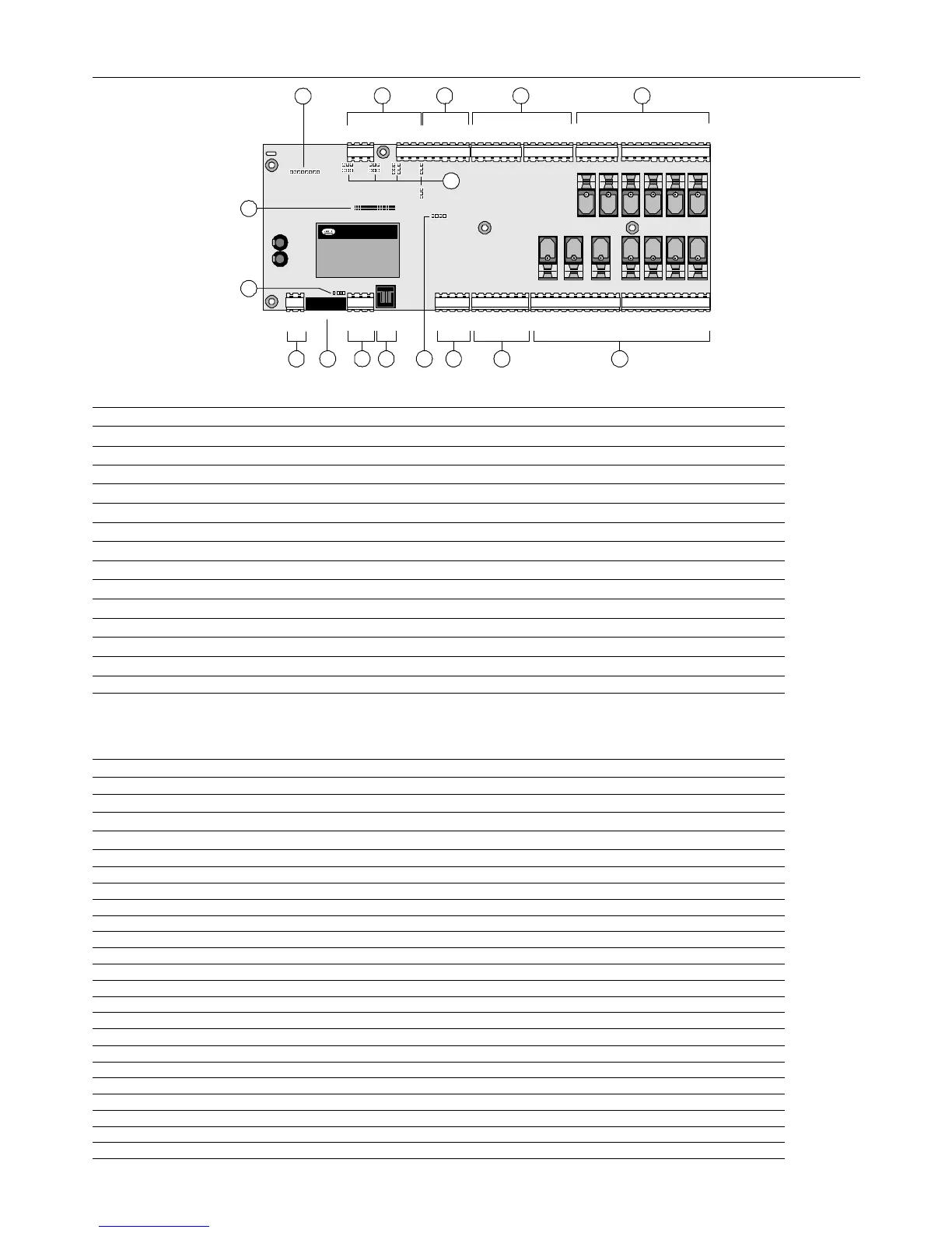
Fig. 2.h
Fig. 2.hFig. 2.h
Fig. 2.h
Key:
Key:Key:
Key:
1. Connector for 24 Vac power supply, 50/60 Hz, 15 VA, or 24 Vdc, 10 W.
2. 250 Vac, 2 A slow-blow fuse (T2A).
3. Yellow mains power LED and 3 status LEDs.
4. Connector for connecting the pCOC boards to the pLAN network (see paragraph 6.3).
5. Telephone connector for connecting a user terminal (PCOT*, PCOI*) or local network.
6. Connector for inserting the optional real time clock board PCO100CLK0.
7. Connector for programming key PCO100KEY0.
8. Connector for inserting the optional supervision and/or telemaintenance boards.
9. Jumpers for selecting the analogue inputs: J14-J3=B5; J15-J10=B6; J28-J11=B7; J29-J12=B8.
10. Universal analogue inputs: NTC, 0/1V, 0/20 mA, 4/20 mA.
11. Passive analogue inputs: NTC.
12. Digital inputs at 24 Vac/Vdc.
13. Relay digital outputs.
14. 230 Vac or 24 Vac/Vdc digital inputs.
15. 0 to 10 V analogue outputs.
2.7.1
2.7.12.7.1
2.7.1 Meaning of the pCO
Meaning of the pCOMeaning of the pCO
Meaning of the pCO
C
CC
C
board inputs/outputs
board inputs/outputsboard inputs/outputs
board inputs/outputs
connector
connectorconnector
connector
signals
signals signals
signals
description
descriptiondescription
description
J17 G power supply, +24 Vdc, 10 W or 24 Vac, 50/60 Hz, 15 VA
J17 G0 power supply reference
J11 RX+/TX+ RX+/TX+ connector for RS485 connection to the pLAN network - Note: different pin conf. from the pCO
3
/pCO
xs
and pCO
1
J11 RX-/TX- RX-/TX- connector for RS485 connection to the pLAN network - Note: different pin conf. from the pCO
3
/pCO
xs
and pCO
1
J11 GND GND connector for RS485 connection to the pLAN network
J19 Terminal connector for terminal 6-pin telephone cable
J20 VG0 power to optically-isolated analogue output, 0 Vac
J20 VG1 power to optically-isolated analogue output, 24 Vac/Vdc
J20 Y1 analogue output 2
J20 Y0 analogue output 1
J21 ID230 Vac digital input 11, 230 Vac
J21 ID24 Vac digital input 11, 24 Vac/Vdc
J21 ID11R common for digital input 11
J21 ——— not connected
J21 ID12R common for digital input 12
J21 ID24 Vac digital input 12, 24 Vac/Vdc
J21 ID230 Vac digital input 12, 230 Vac
J22 NO-11 normally open contact, relay 11
J22 C-11 common for relay 11
J22 NC-11 normally closed contact, relay 11
J22 ——— not connected
J22 NO-10 normally open contact, relay 10
J22 C10 common for relay 10
J22 NC-10 normally closed contact, relay 10
 Loading...


