pCO Sistema
Code: +030220336 - rel. 1.5 - 22/12/10
25
• pCO
pCOpCO
pCO
C
CC
C
mechanical specifications
mechanical specificationsmechanical specifications
mechanical specifications
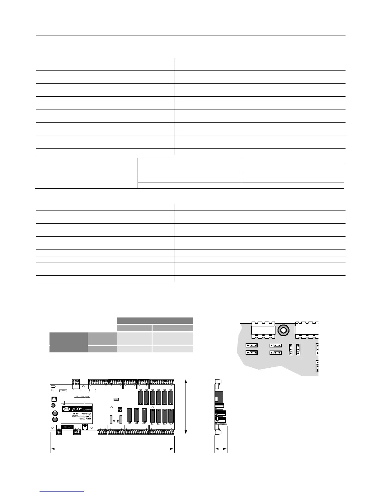
Mechanical dimensions
Electronic board only available, without plastic case: 108 x 292 x 25mm
• pCO
pCOpCO
pCO
C
CC
C
other features
other featuresother features
other features
Operating conditions -10T60°C, 90% RH non-condensing
Storage conditions -20T70°C, 90% RH non-condensing
Index of protection IP20
Environmental pollution 2
Class according to protection against electric shock to be integrated into Class 1 and/or 2 appliances
PTI of the insulating materials 250 V
Period of stress across the insulating parts long
Type of action 1C
Type of disconnection or microswitching microswitching, for all relay outputs
Category of resistance to heat and fire Category D
Immunity against voltage surges Category 1
Ageing characteristics (operating hours) 80,000
No. of automatic operating cycles 100,000 (EN 60730-1); 30,000 (UL 873)
Software class and structure Class A
Category of immunity to voltage surges (IEC EN 61000-4-5) Category 3
Error in the temperature range
typically 6 months (maximum 8 months)
typically 5 hours (<8 hours maximum)
• pCO
pCOpCO
pCO
C
CC
C
electrical specifications
Power supply 24 Vac +10/-15% 50/60 Hz and 22 to 38Vdc +10/-20%
Maximum current with terminal connected P=10 W
Type of insulation of the power supply from the rest of the controller -
Terminal block with male/female plug-in connectors (250 Vac max, 8 A max)
Cable cross-section min 0.5 mm
CPU H8S2320, 16 bit, 14MHz
Program memory (FLASH MEMORY) 1 Mbyte, 16 bit
Data memory (RAM) 128 Kbyte, 8 bit
T memory, buffer (FLASH MEMORY) 4 Kbyte, 16 bit
P memory, parameters (EEPROM) optional (32 Kbyte not available to the pLAN network)
Working cycle duration (application of average complexity) 0.5 s
Clock with battery optional
Procedure for selecting the analogue inputs by jumpers J3, J10, J11, J12, J14, J15, J28 and J29
Procedure for selecting the analogue inputs by jumpers J3, J10, J11, J12, J14, J15, J28 and J29Procedure for selecting the analogue inputs by jumpers J3, J10, J11, J12, J14, J15, J28 and J29
Procedure for selecting the analogue inputs by jumpers J3, J10, J11, J12, J14, J15, J28 and J29
Input B5, B6, B7
Input B5, B6, B7Input B5, B6, B7
Input B5, B6, B7
and B8:
and B8:and B8:
and B8:
J14, J15, J28 and J29
J14, J15, J28 and J29J14, J15, J28 and J29
J14, J15, J28 and J29
1-2 2-3
J3, J10,J11
J3, J10,J11 J3, J10,J11
J3, J10,J11
and J12
and J12and J12
and J12
1-2 4÷20 mA
(default)
0÷1V
2-3 -------------- NTC
pCO
pCOpCO
pCO
C
CC
C
dimensions ( in mm)
dimensions ( in mm)dimensions ( in mm)
dimensions ( in mm)
292
108
25
Fig. 2.h
Fig. 2.hFig. 2.h
Fig. 2.h
J29 J28
J12 J11
J10
J15
J1 J2
3 2 1 3 2 1
3 2 1
B8 B7
B6
 Loading...


