pCO Sistema
Code: +030220336 - rel. 1.5 - 22/12/10
33
4.3.3
4.3.34.3.3
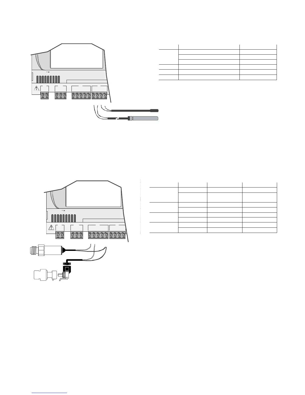
4.3.3 Connecting PT1000 temperature probes
Connecting PT1000 temperature probesConnecting PT1000 temperature probes
Connecting PT1000 temperature probes
The pCO can be connected to 2-wire PT1000 sensors for all high temperature applications; the operating range is: -100 to 200 °C.
The inputs must be configured for PT1000 signals by the application program resident in flash memory.
The connection diagram is shown below:
G
G0
+Vterm
GN D
+5 VREF
VG
V
G0
Y1
Y2
Y3
Y4
ID1
ID2
ID3
ID4
J1 J24 J2 J3
J4
field card serial card
input: 24 V / ;50 to60 Hz
max. power:40 VA/15W
B1
B2
B3
GN D
+VDC
B4
BC4
B5
BC5
Fig. 4.c
Fig. 4.cFig. 4.c
Fig. 4.c
Warnings:
Warnings:Warnings:
Warnings:
• to ensure a correct measurement by the PT1000 sensor, each sensor wire must be connected to a separate terminal, as shown in Figure 4.c;
• the two PT1000 probe wires are equivalent, as there is no polarity, therefore no special order needs to be followed when connecting to the terminal block.
4.3.4
4.3.44.3.4
4.3.4 Connecting pressur
Connecting pressurConnecting pressur
Connecting pressure probes with current signal
e probes with current signale probes with current signal
e probes with current signal
The pCO can be connected to all CAREL SPK* series active pressure probes or any pressure sensor available on the market with a 0 to 20 mA or 4 to 20 mA signal.
The inputs must be configured for 0 to 20 mA or 4 to 20 mA signals by the application program resident in flash memory.
The connection diagram is shown below:
G
G0
+Vterm
GN D
+5 VREF
J1 J24 J2 J3
field card
input: 24 V / ;50 to 60 Hz
max. power:40 VA/15W
B1
B2
B3
GND
+VDC
Fig. 4.d
Fig. 4.dFig. 4.d
Fig. 4.d
 Loading...


