pCO Sistema
Code: +030220336 - rel. 1.5 - 22/12/10
34
G
G 0
+V
ter m
G N D
+5 V
R EF
J1 J24 J2 J3
B1
B2
B3
GND
+V DC
GND
20.5k
out H
M
out T
+ ( G)
4.3.5
4.3.54.3.5
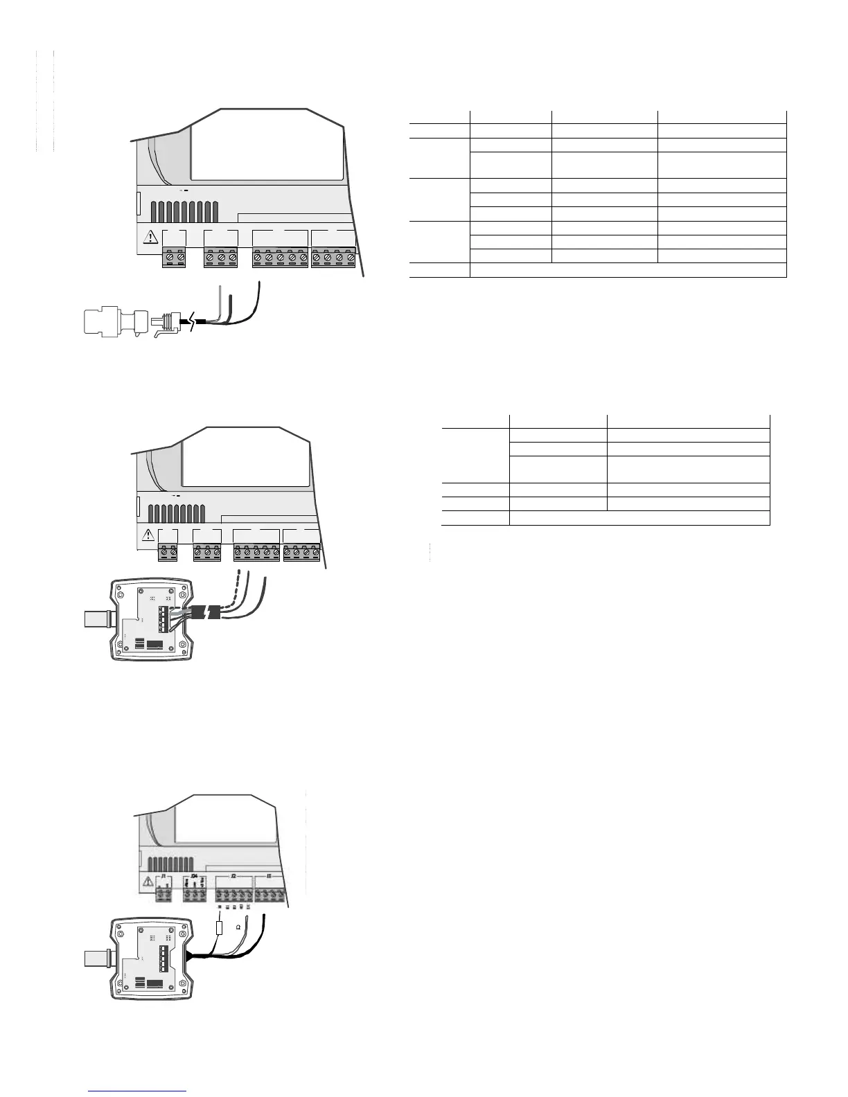
4.3.5 Connecting 0/5 V ratiometric pressure probes
Connecting 0/5 V ratiometric pressure probesConnecting 0/5 V ratiometric pressure probes
Connecting 0/5 V ratiometric pressure probes
The pCO can be connected to all CAREL SPKT series active pressure probes or any pressure sensor available on the market with 0/5 V ratiometric signal. The inputs
must be configured for 0/5V ratiometric signals by the application program resident in the memory.
G
G0
+Vterm
GND
+5VREF
J1 J24 J2 J3
field card
input: 24 V / ;50 to 60 Hz
max. power: 40 VA/15W
B1
B2
B3
GND
+VDC
Fig. 4.e
Fig. 4.eFig. 4.e
Fig. 4.e
4.3.6
4.3.64.3.6
4.3.6 Connecting active probes with 0 to 10 V output
Connecting active probes with 0 to 10 V outputConnecting active probes with 0 to 10 V output
Connecting active probes with 0 to 10 V output
The inputs must be configured for 0 to 10 V signals by the application program resident in flash memory.
G
G0
+Vterm
GND
+5 VREF
VG
V
G0
Y1
Y2
Y3
Y4
ID1
ID2
J1 J24 J2 J3
J4
field card serial card
input: 24 V / ;50 to60 Hz
max. power:40 VA/15W
B1
B2
B3
GND
+VDC
out H
M
out T
+ ( G)
Fig. 4.f
Fig. 4.fFig. 4.f
Fig. 4.f
Reading 0 to 10 V inputs with the pCO
Reading 0 to 10 V inputs with the pCOReading 0 to 10 V inputs with the pCO
Reading 0 to 10 V inputs with the pCO
1
11
1
and pCO
and pCOand pCO
and pCO
XS
XSXS
XS
Warning: the pCO
Warning: the pCOWarning: the pCO
Warning: the pCO
1
11
1
and pCO
and pCOand pCO
and pCO
xs
xsx s
xs
cannot read 0 to 10 Volt inputs.
cannot read 0 to 10 Volt inputs.cannot read 0 to 10 Volt inputs.
cannot read 0 to 10 Volt inputs.
On both controllers, to read this type of input simply set it as 0-5 V at an application level and then fit a 20.5KΩ, 1/4W, 1% resistor in series with terminal Bn, as shown
in the drawing below.
• In this way, for the pCO
pCOpCO
pCO
1
11
1
a measurement error of approx 1.2% is introduced. This error can be easily
overcome by modifying the reading of the analogue input by the application using a gain coefficient of
1.0125, or using two 10K resistors in series instead of one 20.5K.
• For the pCO
pCOpCO
pCO
XS
XSXS
XS
, the following formula must be applied to reading of the analogue input : X= (value of
Ainpco2 – 504 ) * 2.1.
Where: “Value of Ainpco2” is the value of the input read by the software.
Note:
Note: Note:
Note:
• the impedance of the pCO
1
input configured as 0 to 5 V is 20KΩ;
• the impedance of the pCO
xs,
input configured as 0 to 5 V is 6.6KΩ.
The probe must have an output resistance
output resistanceoutput resistance
output resistance that is much lower than the input resistance of the pCO as
indicated above; otherwise the formula applied to the reading will need to be adjusted.
 Loading...


