pCO Sistema
Code: +030220336 - rel. 1.5 - 22/12/10
40
4.6.3
4.6.34.6.3
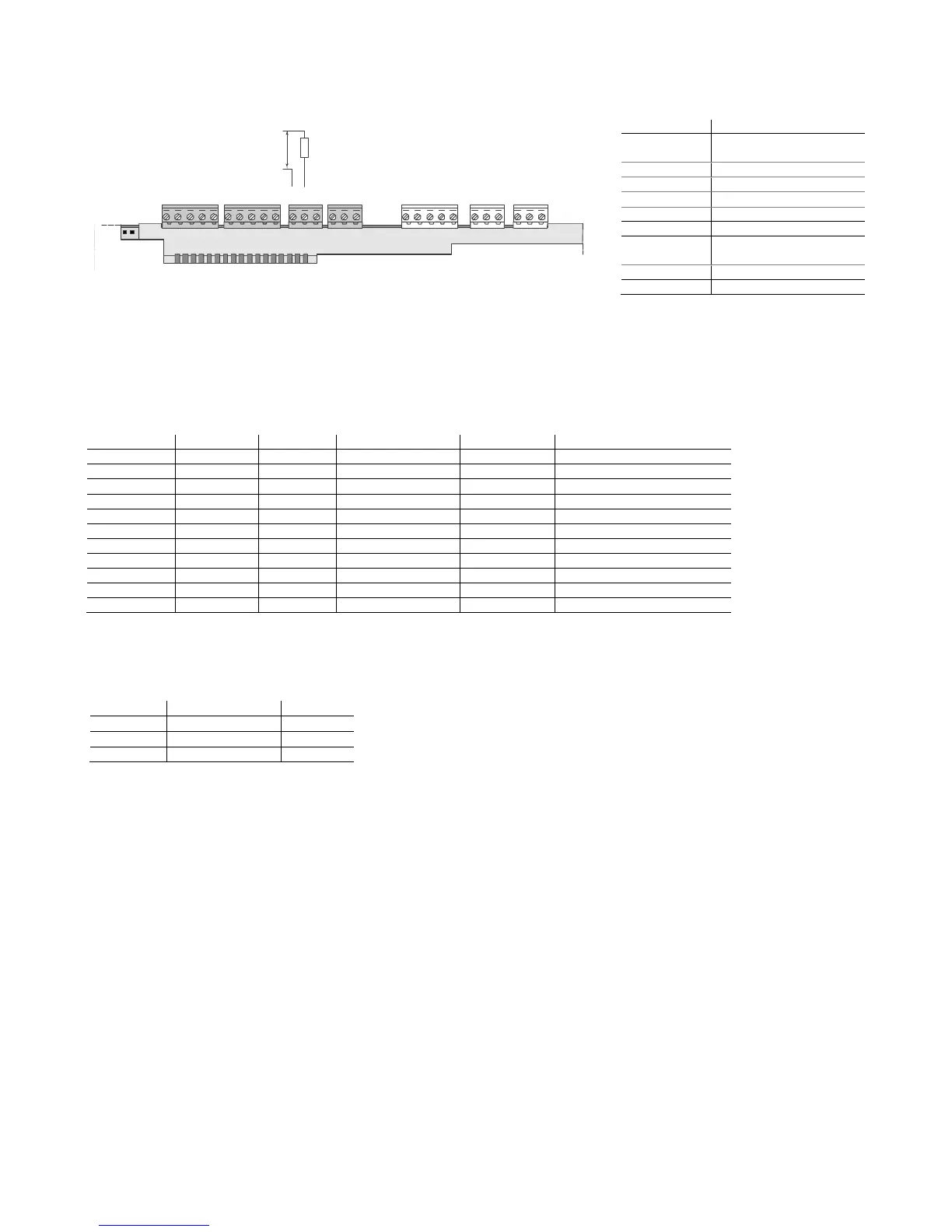
4.6.3 Solid state relay (SSR) digital outputs
Solid state relay (SSR) digital outputsSolid state relay (SSR) digital outputs
Solid state relay (SSR) digital outputs
The pCO also features a version with solid state relays (SSR) for controlling devices which require an unlimited number of switching cycles and thus would not be
supported by electromechanical versions. This outputs are dedicated to loads powered at 24Vac/Vdc with a maximum power Pmax = 10W.
C1
NO1
NO2
NO3
C1
C4
NO4
NO5
NO6
C4
C7
NO7
C7
NO8
C8
NC8
24Vac/Vdc
Fig. 4.p
Fig. 4.pFig. 4.p
Fig. 4.p
Warning:
Warning:Warning:
Warning: the load of the SSR relay is powered at 24Vac/Vdc, thus all the other terminals in the group, from 1 to 6, must be powered with the same tension due to the
absence of double insulation within the group. Moreover, terminals from 1 to 6 can be powered at 110 to 230 Vac using a safety transformer (Class 2).
4.6.4
4.6.44.6.4
4.6.4 Summary table of the digital outputs accor
Summary table of the digital outputs accorSummary table of the digital outputs accor
Summary table of the digital outputs according to the versions available
ding to the versions availableding to the versions available
ding to the versions available
Tab. 4.p
Tab. 4.pTab. 4.p
Tab. 4.p
4.6.5
4.6.54.6.5
4.6.5 Distance of the digital outputs
Distance of the digital outputsDistance of the digital outputs
Distance of the digital outputs
The sizes of the cables used for connecting the digital outputs over a distance are shown in the following table:
Tab. 4.q
Tab. 4.qTab. 4.q
Tab. 4.q
If the product is installed in industrial environments (application of the EN 61000-6-2 standard) the length of the connections must be less than 30m.
In any case, this length should not be exceeded so as to prevent measurement errors.
Relay changeover reference
Relay changeover referenceRelay changeover reference
Relay changeover reference
 Loading...


