8
“manuale thT” +0300077IE - rel. 1.3 - 11.04.2016
ENG
• for the serial connection use three-wire shielded cable, AWG 20-22. The
length of the network must not exceed 500 m. For extended networks
fi t a 120 Ohm resistor between RX/TX+ and RX/TX- on the fi rst and last
device, to avoid possible communication problems.
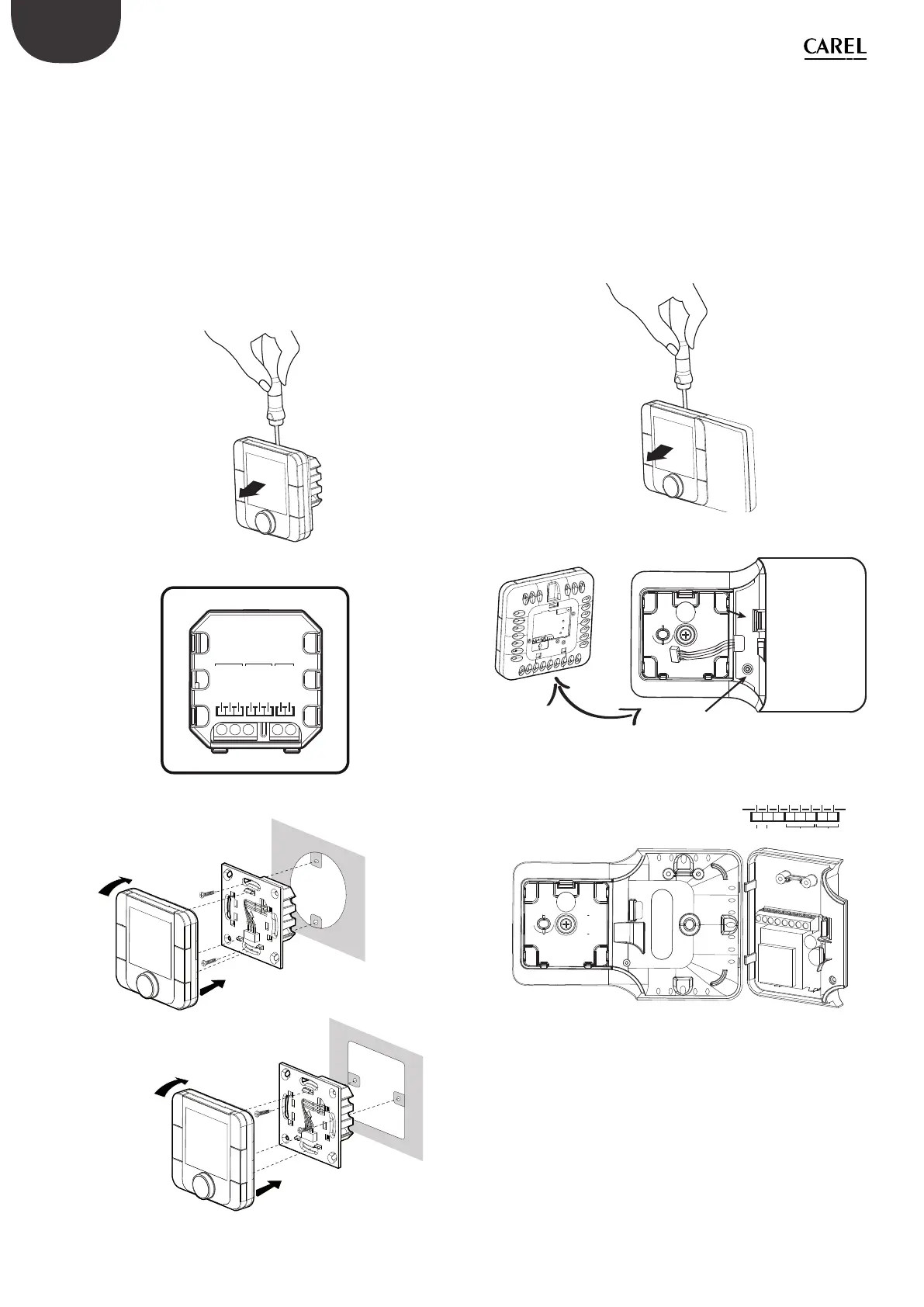
Assembly for the fl ush mounting
To fi t the rear part of the terminal use a fl ush mount box with a min.
diameter of 65 mm and a minimum depth of 31 mm.
1. Detach the front from the rear of the thT thermostat using a
screwdriver;
2. Make the electrical connections according with the schematic;
3. Fasten the rear to the fl ush mount box using the 2 screws supplied:
4. Finally reposition the thT thermostat the original position and ensure
to fi x it with clicks into place.
Dismantling
Wiring
GND
Rx+/Tx+
Rx–/Tx–
GND
A
B
N 230V~
L 50/60Hz
NO
NC
Com
Relay
Power
supply
Serial connections
Exploded
click
4
5
6
click
4
5
6
Assembly for the wall mounting
1. Separate the front from the rear of the terminal using a screwdriver;
2. To remove cover A1, unscrew screw A2 and press the point of
attachment; access terminal block A3;
3. Drill the holes in the wall (dia. 5 mm); then insert the plugs and screws
supplied, making sure that the electrical wires pass through hole E;
4. Make the electrical connections according with the schematic;
5. Close cover A1, completing the same operations as described above
in reverse;
6. Finally reposition the thT thermostat the original position and ensure
to fi x it with clicks into place.
Dismantling
b
Cover dismantling
A1
A2
A3
A3
E
POWER
SUPPLY
Serial connection
RelayAB
Rx+Tx+
Rx-Tx-
GND
NC
Com
NO
N 250 V~
L 50/60 Hz
Is It Possible to change the rotation of the display moving the base in the
other three possible positions:
1. remove the screw;
2. remove the base;
3. turn the base and place it in the right position;
4. tighten the screw;