UltraCella
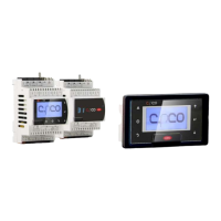
EVD Modules accessories
Power Module –
accessory
1
2
1
2
3
1
2
1
2
3
2
2
1
2
1
2
1
1
N
2
2
1
2
1
2
1
1
1
1
1
2
1
2
1
1
1
2
1
2
2
to option
modules
N
power supply, compressor fan,
actuators
probes, digital inputs
200
290
87,5107,547,5
47,5
30
156
260
32
100
FieldBus
24 Vac
BMS
R6
R5
R4
R3
R2
R1
230 V
EN60730-1
UL 873
250 V
R5 - R6
12 (10) A
12 A res. 2HP
12FLA 72 LRA
CAREL NTC, PT1000
CAREL NTC, PT1000
CAREL NTC, PT1000
CAREL NTC, analog input 0 to 10 Vdc
B5 analog
input
OUT
M
+V
0 to 5 Vdc
DI1
Door switch
B3
B2
B1
48 47 46 45 44 43
49 50 51 52 53 54
VL
GND
GND
Rx/Tx+
Rx/Tx-
GND
Rx/Tx+
Rx/Tx-
GND
Rx/Tx+
Rx/Tx-
GND
Y1
B4
B5
DI1
DI2
DI3
GND
5 VREF
+ Vdc
30
29
28
27
26
25
21
20
19
18
17
16
15
14
13
12
11
10
9
8
7
6
5
4
3
2
1
24
23
22
analog output (0 to 10 Vdc)
EN60730-1
UL 873
250 V
R3 - R4
10 A res.
5 (3) A
10 A res. 5FLA
18 LRA
EN60730-1
UL 873
250 V
R1 - R2
8 (4) A N.O.
8 A res. 2FLA
12 LRA
DEF
CMP
FAN
LIGHT
UltraCella Control
34
35
36
37
38
39
40
41
42
33
32
31
GND
to graphic
terminal display
to remote terminal display
to LED display board
UltraCella - Kontroll för kylrum / Control for cold rooms MONTERING OCH INSTALLATION /
ASSEMBLY AND INSTALLATION
+0500086SV - rel. 2.7 -28.04.2020
NO POWER
& SIGNAL
CABLES
TOGETHER
READ CAREFULLY IN THE TEXT!
Introduktion
UltraCella är en grupp av produkter som
utgörs av en kontroll som hanterar de
grundläggande funktionerna i ett kylrum,
till vilken du kan lägga till olika moduler
för extrafunktioner (t.ex. elektronisk ventil,
effektrelä, etc).
För mer information, se instruktionsboken
(kod. 0300083IT) som finns tillgänglig på
hemsidan www.carel.com, under ”Doku-
ment”.
Huvudegenskaper
UltraCella är en kontroll för kylrum med
enfas kompressor upp till 2HP (upp till
3 HP med tillbehöret effektmodul), som
hanterar kompressorn, förångarfläktar-
na, kondensorfläktarna, dörrlampan och
avfrostning genom elektriska motstånd
eller varm gas. Tillbehören sitter i moduler
som kan kombineras på ett oberoende
sätt till höger om huvudkomponenten,
och bibehålla skyddsgraden IP 65 för hela
uppsättningen
Modeller
Kod Beskrivning
WB000S**F0
LED-display enskild rad
WB000D**F0
LED-display dubbel rad
Tillbehör
Kod Beskrivning
WM00E***00
EVD-modul
WM00P*****
Effektmodul
WT00****N0
TREFASIG effektmodul
PGDEWB0FZ0 UltraCella Service
Introduction
UltraCella is a family of products compri
-
sing a controller for managing the basic
functions of cold room, plus various optio
-
nal modules that can be added for auxilia
-
ry functions (e.g. electronic valve, power
relay, etc.). For more information, read the
operating manual (+0300083EN ), availa
-
ble in the documentation download area
at www.carel.com.
Main features
UltraCella is a controller for cold rooms
with single-phase compressors, up to 2
HP (up to 3 HP with the Power module
accessory) that manages the compressor,
the evaporator fans, the condenser fans,
the door light, and defrost by electric hea
-
ters or hot gas. The accessories are housed
in modules that can be independently
coupled to the right side of the main unit,
maintaining IP 65 ingress protection for
the entire assembly.
Models
P/N Description
WB000S**F0 Single digit LED display
WB000D**F0 Double digit LED display
Accessories
P/N Description
WM00E***00 EVD module
WM00P***** Power module
WT00****N0 THREE-PHASE power module
PGDEWB0FZ0 UltraCella service
Display
1
2
3
4
5
6
7
2
3
4
5
6
1
8
cod. WB000S**F0 cod. WB000D**F0
Teckenförklaring Legenda
1 Huvudfält
Main field
2 Service
Service
3 HACCP
HACCP
4 Öppen dörr
Door open
5 Kompressor
Compressor
6 Förångarfläktar
Evaporator fans
7 Realtidsklocka (RTC)
Real Time Clock (RTC)
8 sekundärt fält
Second field
Tangentbord
Keypad
Knapp /
Key
Beskrivning
Description
• Intryckt i 2 sek, sätter kontrollen
i OFF-läge
• Intryckt i 2 sek, sätter kontrollen
i ON-läge
• Pressed for 2 sec, switches the
controller OFF
• Pressed for 2 sec, switches the
controller ON
• Ger tillgång till programme-
ringsmenyn
• ESC-funktion, återgå till en
högre nivå
• Accesses the programming
menu
• ESC function, return back up
one level
HELP
• I händelse av ett larm: tystas
ljudlarmet (summer)
• Intryckt i 2 sekunder, återställer
larm med manuell återställning
och avaktiverar larmreläet
• In the event of alarms: mutes
the audible alarm (buzzer)
• Pressed for 2 sec, resets the
alarms with manual reset and
deactivates the alarm relay
Tänder/släcker lyset
Light on/off
Slår på/av reservutgång 1
Auxiliary output 1 on/off
Slår på/av reservutgång 2
Auxiliary output 2 on/off
Intryckt längre än 2 sekunder,
aktiverar/avaktiverar manuell
avfrostning
Pressed for 2 sec, activates/deac
-
tivates the manual defrost
Intryckt längre än 2 sekunder
• Aktivera inställningen av bör-
värdet
• Bekräfta värde
Pressed for 2 sec
• Activates the set of the set
point
• Confirms the value
• Ökning / sänkning värde
• Under navigeringen mellan
parametrarna, gå till nästa/
föregående parameter
• Increases / decreases the value
• When browsing the parame
-
ters, moves to the next/pre
-
vious parameter
+
om nedtryckta tillsammans i 2 sek,
tillgång till multifunktionsmenyn
if pressed together for 2 sec, ac
-
cesses the multifunction menu
HACCP – VARNING
Programmen för livsmedelssäkerhet som grundar sig på förfaranden av HACCP-typ och, mer allmänt, i enlighet med vissa nationella lagar, kräver att
den utrustning som används för lagring av livsmedel skall genomgå regelbundna kontroller för att säkerställa att mätningsfelen ligger inom tillåtna
gränsvärden för användning. När temperaturmätningen är viktig för livsmedelssäkerheten, används endast temperaturgivare som föreslagits av Carel.
Mer information angående tekniska egenskaper, korrekt installation och produktens konguration åternns i manualen.
HACCP –
WARNING
The Food Safety programs based on HACCP procedures and on certain national standards, require that the devices used for food preservation are
periodically checked to make sure that the measuring errors are within the allowed limits of the application of use. When the temperature mea
-
surement is important for food safety, only the temperature probes suggested by Carel must be used. The manual contains further indications
regarding technical feature, proper installation and con guration of the product.
CAREL förbehåller sig rätten att göra ändringar på sina produkter utan föregående meddelande.
Carel reserves the right to modify the features of its products without prior notice.
Sätt fast DIN-skenan och
för in kontrollen
Borra de 4 hålen (± 4,5
mm enligt borrmallen)
och sätt i pluggarna
Drill the 4 holes
(
±
4.5 mm based on the
drilling template) and
insert the anchors
Fasten the DIN rail and
attach the controller
Ta bort
ramarna
(1 och 2),
skruva loss
skruvarna
(3) och
öppna
enheten
Remove the
faceplates
(1 and 2),
unscrew the
screws (3)
and open
the panel
Markera positio-
nerna för de nedre
hålen på väggen,
ta bort enheten
och borra hålen
(∅ 4,5 mm); sätt in
pluggarna
Haka återigen fast enheten på DIN-skenan
och fixera den med den nedre skruvarna.
Attach the panel to the DIN rail again and
fasten it by tightening the bottom screws.
Mark the positions
of the bottom
holes on the wall,
remove the panel
and drill the holes
(
±
4.5 mm); insert
the anchors
Ta bort ramarna
(1 och 2)
Skruva loss
skruvarna (2) och
öppna enheten
Skruva
fast
skruvar-
na (1)
och sätt
fast en-
heten
Remove the faceplates
(1 and 2)
Unscrew the screws
(2) and open the
panel
Tighten
the
screws
(1) and
fasten
the
panel
Använd de förborrade hålen och montera
kabelgenomföringarna för anslutning:
• på undersidan: matarkablar, givare,
ställdon;
• på högersidan: anslutningskablar till
eventuella tillbehörsmoduler.
Varning:
• separera kraftkablar (matarspänning,
ställdon) från signalkablar (givare,
digitala ingångar)
• använd en hålsåg för att borra hål i
enheten i överensstämmelse med de
förborrade hålen (A).
Use the knock-outs and fit the cable
glands to connect:
• on the bottom side: power supply, pro
-
be, actuator cables;
• on the right side: the cables for con
-
necting any accessory modules.
Warning:
•
separate the power cable (power sup
-
ply, actuators) from the signal cables
(probes, digital inputs)
• use a holesaw to drill the panel in corre
-
spondence with the predrilled holes (A).
Kopplingsschema /
Wiring diagram
Dimensioner (mm) /
Dimensions (mm)
Borrmall (mm)
Drilling template (mm)
Montering med DIN-skena
DIN rail mounting
Montering med DIN-ske-
na
DIN rail mounting
Bortskaning av produkten. Produkten skall källsorteras separat som fastställts av
lokala bestämmelser angående avfallshantering.
Disposal of the product: The appliance (or the product) must be disposed of separately
in compliance with the local standards in force on waste disposal.
NO POWER
& SIGNAL
CABLES
TOGETHER
READ CAREFULLY IN THE TEXT!
VARNING: Separera givarnas och de digitala ingångarnas kablar så mycket som möjligt
från kablar som hör till de induktiva belastningarna och kraftkablarna för att undvika
elektromagnetiska störningar. Använd aldrig samma kanaler (inklusive de till elskåpen)
till kraftkablar och signalkablar.
WARNING: separate as much as possible the probe and digital input signal cables from
the cables carrying inductive loads and power cables to avoid possible electromagnetic
disturbance. Never run power cables (including the electrical panel wiring) and signal
cables in the same conduits.