Provide
space equat
to €ondenser
length fbr tube
removal
Step
2
-
Receive
Machine
(Fig.
I tuough 8)
BEFORE
UNLOADING
-
Check
unit nameplates
against
model and s€rial
numbers
recorded in
job
specifications
Che\k
all ilems
agdin.t shrpping
list. and examine
items
cdrefull)
tor
dn) shipping damdge.
lt damage
i! found or
anv malor
componenr ha.
rom loo'e
lrom its anchorage
trave
rra'n.ponarion
inspectorr eramine
il belore unloading
File claim
immediateltwith shipping
company
for any loss
or damage.
RIG uNlT CAREFULLY
-
check that rigging
equipment
can safely
handle the approximate
equipment
weights
for
compressors
and cond€nsing
units.
Rig
and move uni'
cdrefully to
prevent damage
Io mounF
ing brackets,
refrigerant
piping
or
connechons
Step
3
-
Install
Unit
To MOUNT
MOTOR ON BASE
-
The motor
fastening
set,
available as an accessory
for all 5F,H
base'mounted
comDressors.
includes
motor blocks
and shims
for motor
alis;menrl
cap screws,
plate
washers and
lock
washen
tor
lan-ening
molor to basea
taper do$el
pins
for securing
mo-
tor ooviion
alter alianmenii
and beveled
ua'her\
for fa=
teniig rhe unir
ba"e io accessory
vibralion
i\olators
II vibration
isolators are used,
attach to base
(Fig.
9) To
avoid damaging
the isolabrs,
lift unit
from ends when
at-
taching
isolators.
With comoressorand
motorDositioned
on the base,
check
the heieht ofthe
vibration isolttors.
Shim between
isolators
and
flo;r ar required
to le!el compressor
base
When level.
.ecurc vibrario; isolators ro floor Check
lhat bevel
washer
(Fis.
9)
is in
place.
condenser
and liquid shutoff
valve connection
facing com-
Dre\sor
end of bdse.
Checl rhar condenser
overhang' sup-
_port
srands
lor same distance on
each end.
Renove
soldered shipping
cap from hol
gas
i.let.
To
pre-
vent solder from dripping
into inlet
pipe while
unsoldering,
rotate condenser
until
pipe
is below
horizontal
position.
Re-
tum inlet
to upight
vedcal
position.
Tishten lower suDDorl
.lraD'
enouqh lo lift conJen\er
off
stand'.. Place upperstrap.
lo6sel)
in po'irion
wrrh
d
.lrip
of
Eotective
material
between condenser
and strap
(5F20
and
5F30
units use lower s$ap
only).
TO MOUNT COMPRESSOR
BASE ON SUPPORT
STANDS
-
Place compressor
base on support
stands with
2 €xtra stdps of
protective
material between
top of con-
denser and base. Bolt
base into
position
with cap screws
and lock washers
provided.
Stop 4
-
Assemble Rsfrigerant
Piping and com-
ponents
-
Refrigerant connection
sizes are
given
in
Table l.
COMPRESSOR
DISCHARGE PIPING
-
Refer to
Condensing
Unit Piping Installation
lnstrLrctions
for
information.
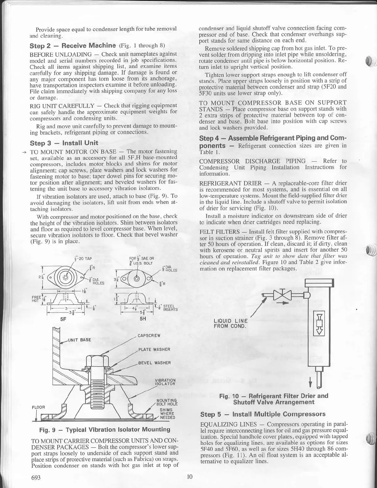
RLFRICERANT DRIER
-
A r€Dlaceable-core
filter drier
is recommended for most svstemi. and is ersenrial
on all
low-remDerature.v.lems.
lvldunr the fi eld-supDlied
liller drier
in the li6uid lrne lnclude a shutoffvalve
ro
dermit
i$lation
of
drier ior servicing
(Fig.
l0).
Install a moisture indicator
on downstr€am side
of dri€r
to indicate
when drier cartridges need
replacing.
FELT FILTERS
-
Install felt filter
supplied with compres-
sor
in suction strainer
(Fig.
3 tbrough 8). Remove
filter af-
ter 50 hours ofoperation.
lfclean, discard
ili ifdirty, cl€an
with kerosene or neutral spirits
and insen for another 50
hours of operation.
Tac unil to show date that
filtet
was
cleaned and leinsta
ed. Figure l0 and Table
2
give
infor-
mation
on replacement filter
packages,
0
,P FoR| sAE oR
I us:s EoLr
1l t ;i1''.,
*t*"
,g[Es
1i
\r
/w\th
5H
LIOUID LINE
FROM COND.
TO
MOTJNT CARRIER
COMPRESSOR
TJNITS AND CON'
DENSER PACKAGES
-
Bolt the
compressor's lowersup-
pon
,lrJp\
loosel]
(o
under.ide
of each
\uppon 'tand
and
Dlace
'rrip' otprotecrive
marrial
(such as Fabricar on sEap.
i'o,irion condin.er
on
'tand. \ irh hol
gas
inlel
ar rop of
693
Fig.
10
-
Refrigerant Filter
Drior and
Shutoff Valve Allangement
Step 5
-
Instsll Multiple Compressors
EQUALIZING
LINES
-
Compressors operating
in
paral-
lelrequire interconnecling
lines lor oil and
ga. pre*ureequal
ilarion.
Spec ial handhole cover
plates.
equ ipped
wilh rapped
holes for equaliring lines.
are atailable as oplions
for siTe'
5F40 and 5F60,
as well as for sizes 5H40
through 86 com-
pressors (Fig.
l1). An oil float system
is an acceptable al-
lemative to equalizer lines.
Fig. I
-
Typical Vibration
lsolstor Mounting
10
 Loading...

