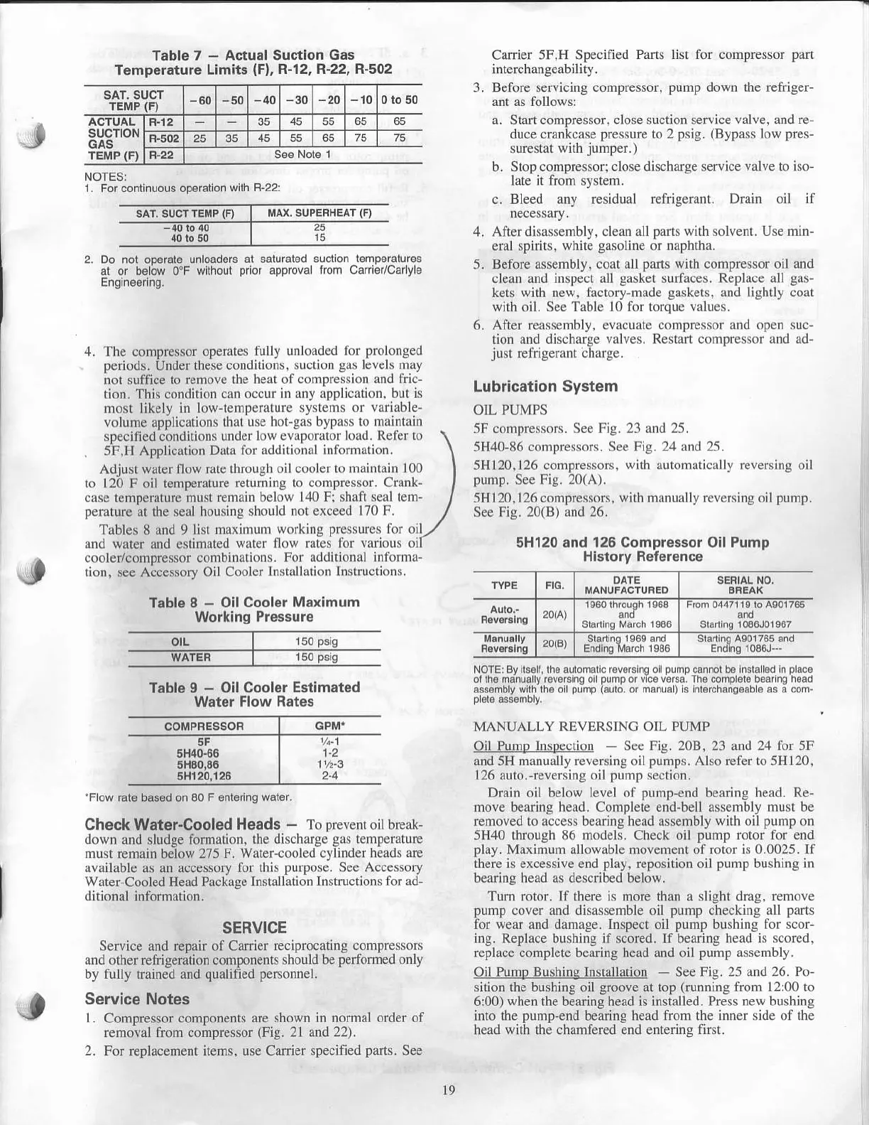
Table 7
-
Actual Suction
Gas
Temperature Limits
(Fl.
R-12, R-22, A-5O2
SAT, SUCT
TEMP
(F)
-60 -40
-30 -20 -10
0ro50
SUCTION
GAS
rEi,tP
{Fl
F.t2 35
45 55 65 65
F.502
25 35 45
55 65 75 75
NOTESI
1 For continuous oporalion
wilh R-22:
Cader sF.H
Specificd Pads
intercbangeabiliry.
3. Before servicing cornpressor.
5.
Start compressor, close srction
service valve. aDd re
duce crankcrse
pressure
to 2
psig.
(Bypass
low
pres-
surestnt with
jumper.)
Srop compre*or. clo.e di.charle
.en
ice
\
dl\e r" i'n
Bleed any rcsidual
refrigerant. Drain oii if
lisr for compressor
pan
pump
down the refiiger-
J
2. Do nol
op€ralo
unloaders al saluraled
al or below 0"F
wilhour
prior
approv8
Engnee.ing.
4. The compressor operates
fuUy unloaded ibr
prolonged
periods.
Under
these conditions, suction
grs levels nray
no! suffice to
remole lhe he,rt of
conlprcssion and tiic-
t;on.
This
condition can occur
in any application. but is
most likely in low tempcrrture
systems or
variable-
volume applications
thrt use hol-gas bypatt to
mai
tain
specified conditions
under low evaponi('
lord. Rcfcr 1o
5F,H Applicdion
Duta tbr
addilionrl inlirrnlrtbn
Adjust water flow rale through
oil coolcr to nlaintain 100
ro 120 F oil temperature
returning to compressor. Crank'
crse temperature hust
rcrnain bclow 140 Fi shali
seal tem
perature
at the
seal housing lhould
not exceed 170 F.
T:rble$
8
and
9
list maximum
worknrg
pressures
lbr oil
lud water and estimated
wrter llow rutes lbr
varous
ol
cooler/compressor conrbin tions.
For additiontrl inli)rnrA-
tion,
see Accessory
Oil Cooler
InstAllati(nr lnslrucli(nrs.
Table I
-
Oil
cooler Maximum
Working Pressure
Table
I
-
Oil Cooler
Estimated
Water
Flow Rates
After
dislssembly, clcan all
pans
with solvenl. Use min-
eral
spirits, white
gasoline
or naphtha.
Before nssenbly. coat all
parls
wilh compressof o'l and
clean and inspect all
gasket
sudaces. Rethce
all gr!
kets
with
new, lactory
nrade gaskets. and lightly cort
with
oil.
See Tablc l0 ior lorque
values.
After rcrssembly. evacuate conrpressor and open ruc
t;on and discharge
valves. Restart conrpressor lnd ad
just
refiigerrnt
chargc.
J
5H40-66
5H80,86
5H120,126
'Flow
ral€ bas6d on 80
F
enteing
wai€r,
Check Water-Cooled
Heads
-
To
prevent
oil break-
down and sludge formation,
the discharge
gas
temperature
must
remain below 275
F. water-cooled cylinder
heads |rre
avaihble
as an
nccessory for this
purpose. See Accessory
water-Cooled
Head Package
Instillation Instruclions tbr ad-
ditional
information.
SERVICE
Seryice and repan of Canier
reciprocating compres$rs
nnd other
refrigeration
components should be
pefonned only
by fully trained and
qualified personnel.
Service Notes
l.
Compressor compone.ti
are shown in nornal order of
removal from compressor
(Fig.
2l and
22).
2. For r€placement items, use Canier specified
parts.
See
Lubrication System
OIL PUMPS
5F compr€ssors. Scc
Fig.23 nd15.
5H40-86 coDpressors. See
Fig. 24 d 25.
5H120,126 compressors,
with a ldnrricrlly reversing
oil
pump.
S€e
Fig.20(A).
5H 120,126
cornp.essors, wilh mrnurlly rcvcNing oil
purrrp.
See Fig. 20(B) rnd 26.
5H120 and 126 Compressor Oil Pump
History Reterence
NOTE] By ls6li,lh6 aulomaiic rove.sing oilpumpcannotbo nslaled n
placo
ollhe manuaLy rove6ing
oil
pump
or v ce v6rea Tri6
complel€
b€arng rroad
assdmbly wlh ih6 o
pump
laulo
or manual) s ni€rchanoeab6 as a com
MANUALLY
REVERSINC OIL PUMP
Oil Punrp hrsnecti{'r Scc
Fig.
208. 23 .ud
24 for
5F
and 5H nunually reversirg oil
pumps.
Also refcr
to
5H120,
126 auto.
revcrsing oil punrp scction.
Drain oil below level ol
punp
end bcnring head. Re-
move bearing head. Complete end-bell assembly Dusl be
renroved !o access beariDg head assembly
wi!h
oil
pump
on
5H40 through
86 nn)dels.
Check oil
pump rotor for end
phy. M.rximunr allowlble movement
of
rotor is 0.0025. If
there is excessive end
play,
reposition oil
pump
bushing in
bearing head as described below.
Turn rotor. lf lhere is more than a slight drrg,
remove
punrp
cover
xnd disrssemble oil pump checking all
parts
for wear and damage. Inspect oil
pump
bushing for scor-
ins. Replace bushins if scored. If bearing
head is scorcd,
replace
complete bearing head and oil
pump rssembly.
Oil Pump Bushinq Installation
-
See Fig. 25
rnd 16. Po
sition ihe bushing oil
groove
at top
(running
fronl l::00 to
6:00) when the bearing head is installed. Press new bushing
into the
pump-end
bearing head
from the inner side of thc
head with the
chrmfered
eDd entering firsl.
couPREssoR
1.2
11/2-3
2'4
l9
 Loading...

